개요
이 장은 뒤의 전송, 네트워크, 인터넷 프로토콜 내용을 하나의 틀 안에 놓기 위해 protocol architecture를 소개한다. 핵심 관점은 통신 기능을 한 덩어리로 구현하지 않고, 서로 의존하는 계층(layer)으로 나누어 하드웨어와 소프트웨어가 데이터를 교환하게 만든다는 것이다. 가장 널리 쓰이는 구조는 TCP/IP protocol suite이고, 비교 기준으로 OSI(Open Systems Interconnection) model도 함께 다룬다.
핵심 개념
Protocol architecture: 시스템 사이의 데이터 교환과 전자우편, 파일 전송 같은 distributed application을 지원하는 layered structure다.Protocol: 두 시스템의 peer layer가 데이터를 교환할 때 따르는 규칙 집합이다. 형식, 의미, 시간 조건을 함께 포함한다.TCP/IP protocol suite: physical, network access, internet, transport, application layer로 설명되는 인터넷 중심 protocol architecture다.OSI model: 7계층 reference model이다. 실제 구현으로는 TCP/IP보다 덜 쓰이지만, 통신 기능을 설명하고 표준화 범위를 나누는 기준틀로 중요하다.
세부 정리
2.1 The Need for a Protocol Architecture
컴퓨터나 단말이 데이터를 주고받는 절차는 단순한 “비트 전송”보다 훨씬 복잡하다. 예를 들어 두 컴퓨터 사이에서 파일을 전송하려면 먼저 직접 통신 경로를 활성화하거나 통신 네트워크에 destination system의 identity를 알려야 한다. 그다음 destination system이 데이터를 받을 준비가 되었는지 확인해야 하고, destination의 file management program이 특정 사용자에 대해 파일을 받아 저장할 준비가 되었는지도 확인해야 한다. 두 시스템의 file format이 다르면 format translation도 필요하다.
이런 기능을 하나의 거대한 module로 구현하면 변경과 이해가 어려워진다. 그래서 protocol architecture는 통신 작업을 여러 subtask로 나누고, 이 subtask들을 vertical stack의 layer로 배열한다. 각 layer는 통신에 필요한 관련 기능 일부를 수행하고, 더 primitive한 기능은 아래 layer에 의존한다. 동시에 위 layer에는 service를 제공한다. 이상적으로는 한 layer의 구현이 바뀌어도 다른 layer는 바뀌지 않아야 한다.
계층 구조에서 실제 통신은 같은 위치의 peer layer 사이에서 이루어진다고 본다. 두 시스템에는 같은 layered function set이 있고, 각 peer layer는 정해진 규칙에 맞는 formatted block of data를 주고받는다. 이 규칙이 protocol이다.
Protocol의 세 가지 핵심 특징은 다음과 같다.
| 특징 | 의미 | 예시 질문 |
|---|---|---|
Syntax | data block의 format, 필드 배치, 비트 표현 | header와 payload는 어디에 놓이는가? |
Semantics | coordination과 error handling을 위한 control information의 의미 | 이 control field는 ACK인가, 오류 표시인가? |
Timing | speed matching, sequencing, 전송 순서와 시점 | 언제 보내고, 어떤 순서로 처리하며, 상대 속도 차이를 어떻게 맞추는가? |
이 절의 중요한 결론은 protocol architecture가 “복잡한 통신 기능을 계층별 책임으로 분해하는 설계 원리”라는 점이다. Appendix 2A의 TFTP(Trivial File Transfer Protocol)는 이 장 끝에서 protocol이 실제 packet format과 동작 절차로 어떻게 구체화되는지 보여주는 예시로 쓰인다.
2.2 The TCP/IP Protocol Architecture
TCP/IP protocol architecture는 ARPANET 연구개발에서 나온 protocol suite다. 하나의 protocol이 아니라 Internet standards로 제정된 큰 protocol collection이며, 컴퓨터 통신 표준을 개발하는 실질적 틀로 쓰인다.
The TCP/IP Layers
통신에는 크게 application, computer, network 세 agent가 관여한다. File transfer나 electronic mail 같은 distributed application은 두 computer system 사이의 데이터 교환을 필요로 하고, computer는 여러 application을 동시에 실행할 수 있으며, network는 한 computer에서 다른 computer로 데이터를 옮긴다. 따라서 데이터 전달은 먼저 올바른 computer까지 가야 하고, 그 computer 안에서 올바른 application/process까지 가야 한다.
TCP/IP는 이 작업을 다섯 layer로 나눈다.
| TCP/IP layer | 핵심 책임 | 대표 질문 |
|---|---|---|
Physical layer | data transmission device와 transmission medium/network 사이의 physical interface | 신호 특성, data rate, 매체 특성은 무엇인가? |
Network access layer | end system과 직접 붙은 network 사이의 데이터 교환 | 같은 network 안에서 destination device까지 어떻게 보낼 것인가? |
Internet layer | 여러 interconnected network를 가로지르는 routing | source와 destination이 다른 network에 있을 때 어떤 router들을 거칠 것인가? |
Transport layer 또는 Host-to-host layer | application 사이의 reliable exchange, ordering, flow/error control | 모든 데이터가 순서대로, 손상 없이 목적 application에 도착했는가? |
Application layer | 사용자 application별 통신 logic | file transfer, e-mail, remote login 같은 기능은 어떤 protocol logic을 쓰는가? |
Network access layer를 별도 layer로 둔 이유는 network 종류가 다양하기 때문이다. Circuit switching, packet switching(frame relay), LAN(Ethernet) 등은 각각 다른 access standard를 가진다. 이 layer가 network-specific detail을 감추면, 그 위의 communication software는 컴퓨터가 어떤 network에 붙어 있는지에 덜 의존한다.
Internet layer는 서로 다른 network에 붙은 두 end system이 통신하게 한다. 여기서 핵심 protocol은 IP(Internet Protocol)이고, IP는 end system뿐 아니라 router에도 구현된다. Router는 두 network를 연결하고 source에서 destination까지 가는 경로 위에서 데이터를 한 network에서 다음 network로 relay한다.
Transport layer는 application 종류와 비교적 독립적으로 reliability를 제공한다. 모든 데이터가 destination application에 도착했는지, 보낸 순서대로 도착했는지, flow가 너무 빠르지 않은지, 손상되거나 잃어버린 segment를 어떻게 회복할지를 다룬다. 가장 대표적인 transport protocol은 TCP(Transmission Control Protocol)이다. 반대로 Application layer는 application 종류마다 필요한 logic이 달라서, file transfer 같은 기능별 module이 따로 존재한다.
Operation of TCP and IP
Figure 2.1은 TCP/IP 통신에서 host, application, port, IP, router, subnetwork가 어떻게 연결되는지 보여준다. 전체 통신 시설은 여러 network로 이루어질 수 있으므로 구성 network를 subnetwork라고 부른다. Host는 Ethernet 같은 network access protocol로 subnetwork에 붙고, target host가 다른 subnetwork에 있으면 router가 데이터를 forwarding한다.
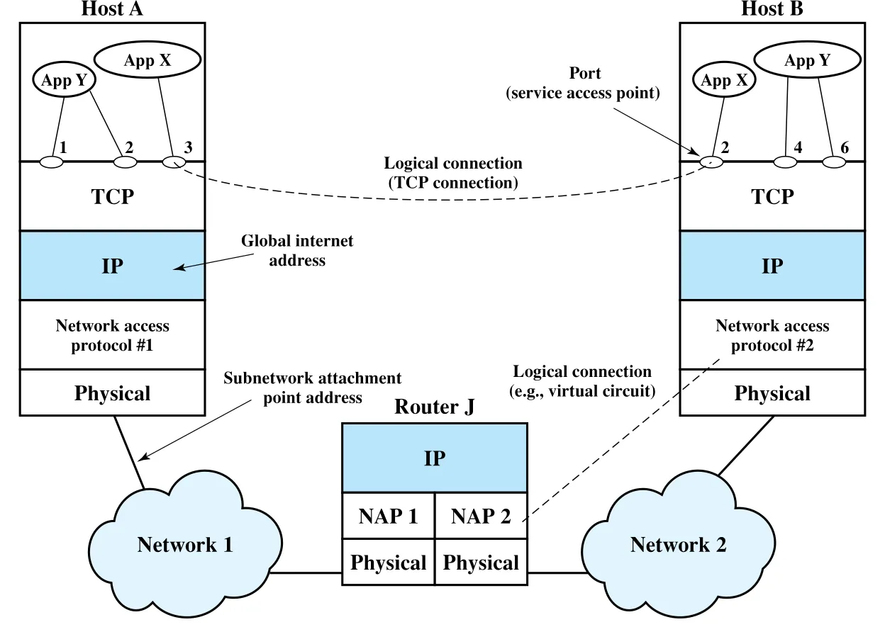 Figure 2.1 · PDF p. 55 · TCP/IP에서 application, port, IP, router, subnetwork가 연결되는 방식
주소는 두 수준이 필요하다. 첫째, 각 host는 subnetwork 위에서 고유한 global internet address를 가져야 한다. 그래야 데이터가 올바른 host까지 도착한다. 둘째, host 안의 각 process는 그 host 안에서 고유한 address를 가져야 한다. 이 process address가 port다. TCP는 port를 보고 데이터를 올바른 process/application에 넘긴다.
예를 들어 Host A의 port 3 process가 Host B의 port 2 process로 메시지를 보낸다고 하자. A의 process는 메시지를 TCP에 넘기며 “Host B, port 2로 보내라”고 지시한다. TCP는 이를 IP에 넘기며 “Host B로 보내라”고 한다. IP는 destination port를 알 필요가 없다. IP의 관심사는 host B까지 가는 것이고, port는 transport layer가 처리한다. 다음으로 IP는 network access layer에 첫 hop인 router J로 보내라고 지시한다.
Figure 2.2는 user data가 layer를 내려가며 control information을 덧붙이는 encapsulation 흐름을 보여준다. Sending process가 만든 user data block은 TCP로 내려가고, TCP는 이를 더 작은 piece로 나눌 수 있다. 각 piece에는 TCP header가 붙어 TCP segment가 된다. TCP header에는 destination port, sequence number, checksum 같은 control information이 들어간다.
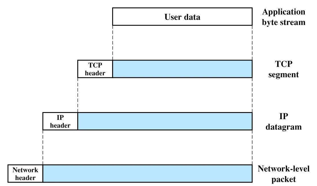 Figure 2.2 · PDF p. 56 · user data가 TCP segment, IP datagram, network-level packet으로 encapsulation되는 흐름
TCP segment는 IP로 내려가고, IP는 각 segment에 IP header를 붙여 IP datagram을 만든다. IP header의 대표 정보는 destination host address다. 마지막으로 network access layer는 IP datagram에 network header를 붙여 packet 또는 frame을 만든다. 이 header에는 destination subnetwork address나 priority 같은 facilities request가 들어갈 수 있다.
Router J에서는 network-level header가 제거되고 IP header가 검사된다. Router의 IP module은 destination address를 바탕으로 datagram을 다음 subnetwork로 내보낸다. 이때 그 subnetwork에 맞는 network access header가 다시 붙는다. Destination host B에 도착하면 반대 과정이 일어난다. 각 layer가 자기 header를 제거하고 나머지를 위 layer로 넘겨, 최종적으로 원래 user data가 destination process에 전달된다.
TCP and UDP
TCP는 대부분의 TCP/IP application이 사용하는 transport layer protocol이다. TCP는 application 사이에 reliable connection을 제공한다. 여기서 connection은 두 system의 entity 사이에 만들어지는 temporary logical association이며, 더 구체적으로는 특정 port pair와 연결된다. Connection이 유지되는 동안 양쪽 TCP entity는 segment의 흐름을 추적해 flow를 조절하고, lost segment나 damaged segment를 회복한다.
Figure 2.3a의 TCP header는 최소 20 octets(160 bits)다. Source Port와 Destination Port는 connection을 사용하는 source/destination application을 식별한다. Sequence Number, Acknowledgment Number, Window는 flow control과 error control에 쓰인다. Checksum은 TCP segment 오류 검출을 위한 16-bit frame check sequence다.
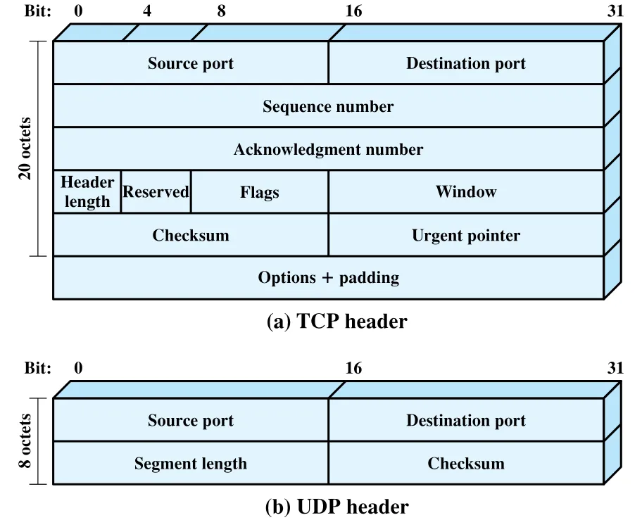 Figure 2.3 · PDF p. 58 · TCP header와 UDP header의 필드 구성 비교
UDP(User Datagram Protocol)는 TCP와 달리 delivery, sequence preservation, duplication protection을 보장하지 않는다. 대신 최소한의 protocol mechanism으로 한 procedure가 다른 procedure에 message를 보낼 수 있게 한다. UDP는 connectionless이므로 해야 할 일이 적고, 본질적으로 IP에 port addressing capability를 더하는 역할에 가깝다. 그래서 UDP header는 source port, destination port, segment length, checksum으로 단순하다. Checksum은 data error 검사용이지만 사용은 optional이다. 원문 예시는 transaction-oriented application인 SNMP(Simple Network Management Protocol)가 UDP를 사용할 수 있음을 보여준다.
TCP와 UDP의 trade-off는 명확하다.
| 구분 | TCP | UDP |
|---|---|---|
| 연결 성격 | logical connection 기반 | connectionless |
| 제공 기능 | reliable delivery, ordering, flow/error control | port addressing 중심의 최소 기능 |
| overhead | header와 상태 관리가 큼 | header와 처리 부담이 작음 |
| 적합한 상황 | 파일 전송, 웹, 메일처럼 정확성이 중요한 경우 | 관리 메시지, 단순 request/response, application이 자체 제어를 하는 경우 |
IP and IPv6
TCP/IP architecture의 keystone은 IP(Internet Protocol)다. Figure 2.4a의 IPv4 header는 최소 20 octets이고, transport layer에서 내려온 segment와 함께 IP datagram 또는 IP packet을 이룬다. Header에는 32-bit source address와 destination address가 들어간다. Header Checksum은 header 오류를 검출해 잘못된 전달을 피하게 하고, Protocol field는 IP 위에서 어떤 higher-layer protocol이 쓰이는지 나타낸다. ID, Flags, Fragment Offset은 fragmentation and reassembly에 쓰인다.
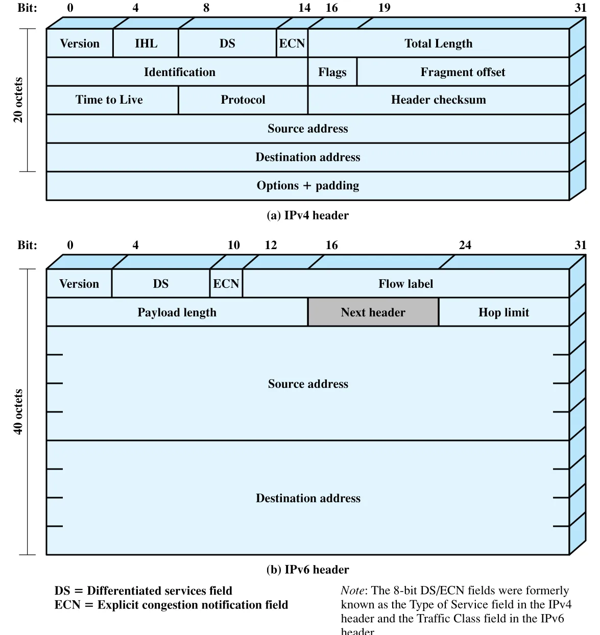 Figure 2.4 · PDF p. 59 · IPv4 header와 IPv6 header의 주요 필드와 주소 길이 차이
IPv6는 더 높은 network speed와 graphic/video 같은 data stream 증가에 맞춘 기능 개선을 담지만, 원문이 강조하는 가장 큰 동기는 address 부족이다. IPv4는 source/destination에 32-bit address를 쓰는데, Internet과 Internet에 연결된 private network가 폭발적으로 늘면서 이 길이로는 충분하지 않게 되었다. IPv6는 source/destination address field를 128-bit로 확장한다. 전환은 최종적으로 필요하지만, 모든 TCP/IP 설치가 IPv6로 옮겨 가는 데는 오랜 시간이 걸린다.
TCP/IP Applications
TCP 위에서 동작하도록 표준화된 대표 application protocol은 다음과 같다.
| Application protocol | 역할 | TCP와의 관계 |
|---|---|---|
SMTP(Simple Mail Transfer Protocol) | host 사이에서 electronic mail message를 전송 | 메시지를 만든 뒤 TCP로 상대 SMTP module에 전달 |
FTP(File Transfer Protocol) | 사용자 명령에 따라 file을 한 system에서 다른 system으로 전송 | control message용 TCP connection과 data transfer용 TCP connection을 분리 |
TELNET | remote logon 기능 제공 | User TELNET과 Server TELNET 사이 terminal traffic을 TCP connection으로 운반 |
FTP의 연결 분리는 특히 기억할 만하다. User ID, password, file action 같은 제어 메시지는 control connection으로 교환되고, 실제 file data는 별도의 data connection으로 전송된다. Data connection에서는 application-level header나 control information overhead 없이 file을 옮긴다. 전송 완료 후에는 control connection으로 completion을 알리고 새 명령을 받을 수 있다.
Protocol Interfaces
TCP/IP architecture에서는 일반적으로 각 layer가 바로 위아래 layer와 상호작용한다. Source에서는 application layer가 end-to-end/transport layer service를 사용하고, transport layer는 internet layer를, internet layer는 network access layer를 사용한다. Destination에서는 각 layer가 데이터를 위 layer로 전달한다.
하지만 architecture가 반드시 모든 application이 모든 layer를 순서대로 쓰도록 강제하는 것은 아니다. Figure 2.5처럼 대부분의 application은 reliable end-to-end protocol이 필요해 TCP를 쓰지만, 어떤 special-purpose application은 TCP 대신 UDP를 사용하고, 다른 application은 IP를 직접 쓰거나 network access layer를 직접 invoke할 수도 있다. 즉 TCP/IP suite는 고정된 한 줄 경로가 아니라, 요구하는 service에 따라 protocol을 선택하는 구조다.
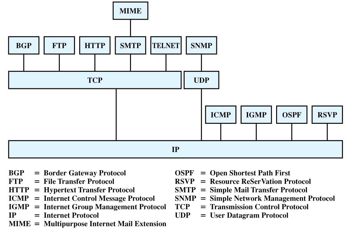 Figure 2.5 · PDF p. 61 · TCP/IP protocol suite 안에서 application protocol, TCP/UDP, IP, routing/control protocol이 놓이는 위치
2.3 The OSI Model
OSI(Open Systems Interconnection) reference model은 ISO가 computer protocol architecture의 모델이자 protocol standard 개발 framework로 만든 7계층 구조다. OSI는 실제 인터넷 구현의 주류가 되지는 못했지만, 통신 기능을 설명할 때 계층별 책임을 분리하는 reference model로 여전히 중요하다.
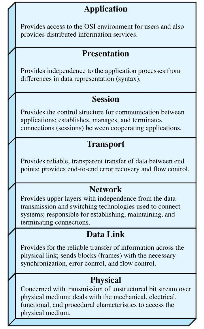 Figure 2.6 · PDF p. 62 · OSI 7계층과 각 계층의 기본 기능
OSI 7계층은 다음처럼 이해하면 좋다.
| OSI layer | 핵심 기능 |
|---|---|
Application | 사용자에게 OSI environment access와 distributed information service 제공 |
Presentation | data representation, 즉 syntax 차이로부터 application process를 독립시킴 |
Session | application 사이 communication control structure 제공, session의 establish/manage/terminate 담당 |
Transport | endpoint 사이 reliable, transparent data transfer, end-to-end error recovery와 flow control 제공 |
Network | data transmission/switching technology 차이를 upper layer로부터 숨기고 connection 설정·유지·종료 담당 |
Data Link | physical link 위에서 frame 단위 reliable transfer, synchronization/error control/flow control 제공 |
Physical | physical medium 위의 unstructured bit stream 전송, mechanical/electrical/functional/procedural 특성 처리 |
원래 OSI 설계자는 OSI model과 그 안에서 개발된 protocol들이 proprietary protocol과 TCP/IP 같은 경쟁 multivendor model을 대체할 것으로 기대했다. 그러나 실제로는 TCP/IP architecture가 지배적이 되었다. 가장 큰 이유는 interoperability 요구가 커질 당시 TCP/IP 핵심 protocol이 이미 mature하고 well tested였지만, OSI protocol은 아직 개발 단계였다는 점이다. 또 OSI는 TCP/IP가 더 적은 layer로 처리하는 기능을 7 layer로 나누어 불필요하게 복잡하다는 평가도 받았다.
Figure 2.7은 OSI와 TCP/IP layer의 대략적 대응을 보여준다. TCP/IP의 application layer는 OSI의 application, presentation, session 기능을 상당 부분 포괄한다. TCP/IP transport layer는 OSI transport와 대응하고, TCP/IP internet layer는 OSI network와 대응한다. TCP/IP network access layer는 OSI data link와 일부 physical 접근 기능을 포함하는 식으로 이해할 수 있다.
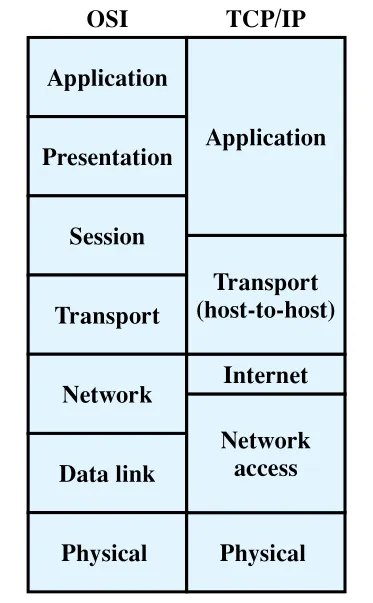 Figure 2.7 · PDF p. 63 · OSI 7계층과 TCP/IP 계층의 기능 대응
2.4 Standardization Within a Protocol Architecture
OSI model이 개발된 중요한 동기 중 하나는 표준화를 위한 framework를 제공하는 것이다. Model이 각 layer의 기능을 일반적으로 정의하면, 각 layer마다 하나 이상의 protocol standard를 독립적으로 만들 수 있다. Layer 기능과 boundary가 잘 정의되어 있으면 두 가지 장점이 생긴다. 첫째, layer별 standard를 독립적이고 동시에 개발할 수 있어 standards-making process가 빨라진다. 둘째, 한 layer의 standard가 바뀌어도 다른 layer의 software를 꼭 바꾸지 않아도 되어 새 standard를 도입하기 쉽다.
Figure 2.8은 OSI architecture가 modularity와 information hiding을 통해 전체 communication function을 분해하는 방식을 보여준다. Lower layer는 더 세부적인 전송 문제를 다루고, upper layer는 그 세부에서 독립적이다. 각 layer는 위 layer에 service를 제공하고, 다른 system의 peer layer와 protocol을 구현한다. 이 원리는 OSI뿐 아니라 TCP/IP architecture에도 적용된다.
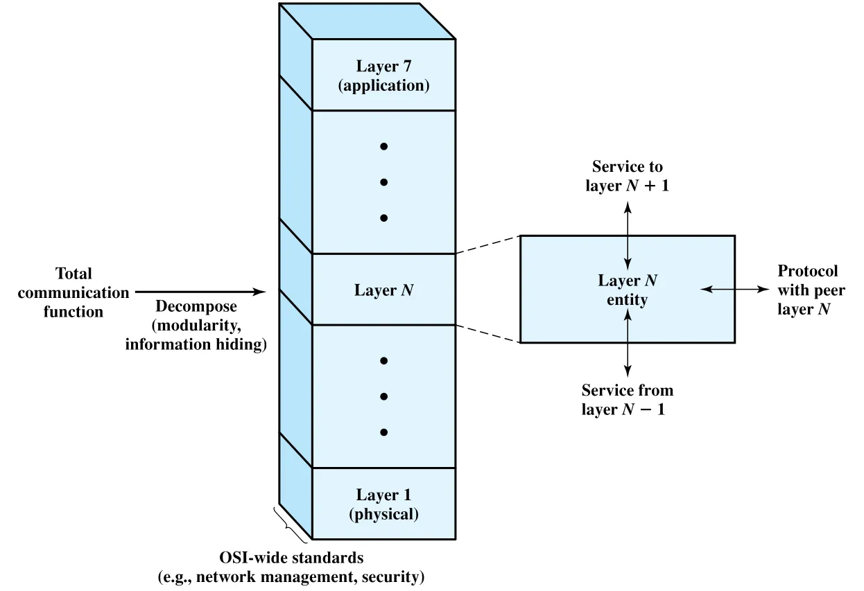 Figure 2.8 · PDF p. 64 · OSI architecture를 표준화 framework로 사용하는 방식
Layer별 standardization에는 세 가지 요소가 필요하다.
| 요소 | 의미 | 왜 필요한가 |
|---|---|---|
Protocol specification | peer layer entity 사이에서 교환되는 PDU format, field semantics, allowable PDU sequence를 정확히 명세 | 서로 다른 open system이 같은 protocol로 상호운용되려면 syntax와 semantics가 정확해야 함 |
Service definition | 한 layer가 바로 위 layer에 제공하는 service를 functional description으로 정의 | 무엇을 제공하는지만 정의하고, 내부적으로 어떻게 제공하는지는 system별 최적화를 허용 |
Addressing | 위 layer entity를 참조하기 위한 SAP(Service Access Point) 사용 | 한 layer가 위 layer의 여러 user를 multiplex할 수 있게 함 |
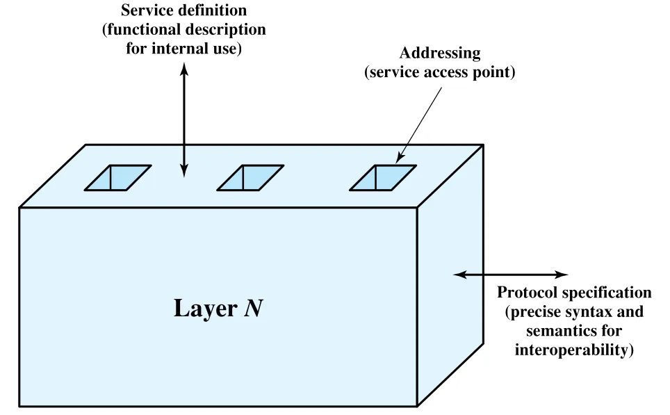 Figure 2.9 · PDF p. 65 · protocol specification, service definition, addressing으로 구성되는 layer-specific standards
Service definition을 “기능 설명” 수준으로 둔 이유는 인접 layer 사이의 interaction이 한 open system 내부에서 일어나기 때문이다. 다른 system과 직접 맞춰야 하는 것은 peer layer 간 protocol이고, 한 system 내부에서 위아래 layer가 어떻게 interface하는지는 interoperability를 해치지 않는 한 구현자가 hardware와 operating system을 활용해 효율적으로 만들 수 있다.
Addressing은 각 layer에서 여러 upper-layer user를 구분하기 위한 장치다. NSAP(Network Service Access Point)는 network service를 사용하는 transport entity를 가리키는 식이다. Multiplexing이 모든 layer에서 항상 일어나지는 않지만, SAP 기반 주소 체계는 그 가능성을 열어 둔다.
Service Primitives and Parameters
OSI architecture에서 adjacent layer 사이의 service는 primitive와 parameter로 표현된다. Primitive는 수행할 function을 지정하고, parameter는 data와 control information을 전달한다. 실제 primitive 형태는 implementation-dependent이며, procedure call이 한 예가 될 수 있다.
| Primitive | 의미 |
|---|---|
Request | service user가 어떤 service를 invoke하고 필요한 parameter를 넘길 때 발행 |
Indication | service provider가 peer service user의 procedure 호출 또는 provider-initiated action을 service user에게 알릴 때 발행 |
Response | indication으로 호출된 procedure를 service user가 acknowledge 또는 complete할 때 발행 |
Confirm | request로 호출된 procedure를 service provider가 acknowledge 또는 complete할 때 발행 |
Figure 2.10a의 confirmed service는 request, indication, response, confirm이 모두 관여한다. Source의 N-entity가 N-1 entity에 request primitive를 내고, N-1 entity가 peer N-1 entity로 PDU를 보낸다. Destination N-1 entity는 indication primitive로 destination N-entity에 data와 source address를 전달한다. Acknowledgment가 필요하면 destination N-entity가 response를 내고, source N-entity는 confirm을 받는다. Initiator가 요청한 action이 상대편에서 원하는 효과를 냈다는 확인을 받는 구조다.
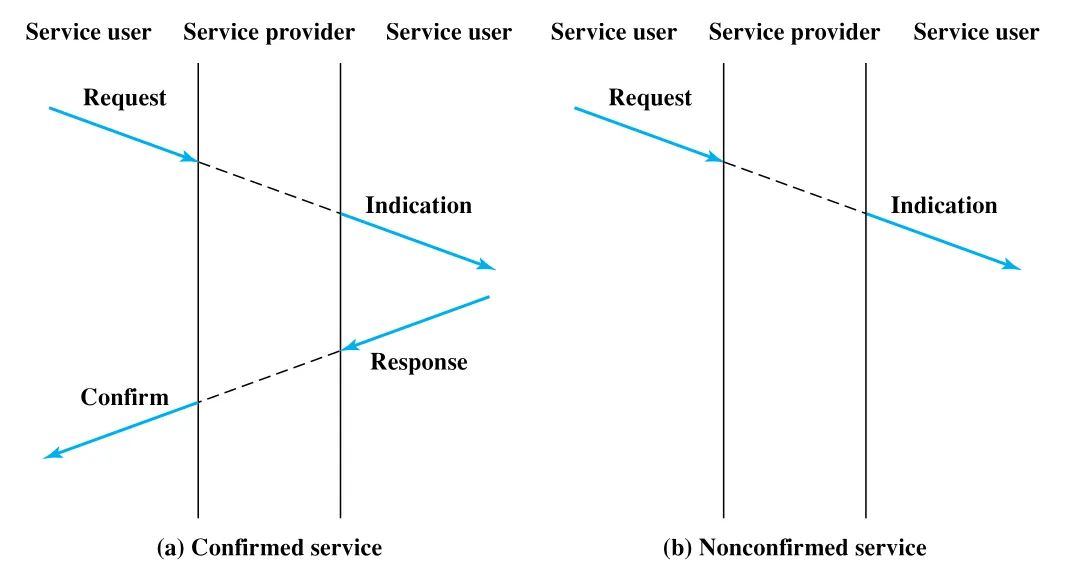 Figure 2.10 · PDF p. 66 · confirmed service와 nonconfirmed service의 primitive 시간 순서
반대로 nonconfirmed service는 request와 indication만 관여한다. Initiator는 요청 action이 실제로 수행되었는지 confirm을 받지 않는다. 이 차이는 protocol 설계에서 reliability와 overhead 사이의 trade-off를 이해하는 좋은 출발점이다.
2.5 Traditional Internet-Based Applications
이 절은 TCP 위에서 동작하도록 표준화된 대표 Internet-based application을 다시 독립적으로 정리한다. 앞의 TCP/IP applications 설명과 같은 세 protocol이 반복되지만, 여기서는 “application protocol이 TCP service를 어떻게 사용해 사용자 기능을 구성하는가”에 초점이 있다.
SMTP(Simple Mail Transfer Protocol)는 기본 electronic mail transport facility다. SMTP는 message를 작성하는 방법 자체를 정하지 않는다. 사용자는 local editing tool이나 native e-mail facility로 message를 만들고, SMTP는 완성된 message를 받아 TCP를 사용해 다른 host의 SMTP module로 전달한다. Target SMTP module은 local e-mail package를 사용해 incoming message를 사용자의 mailbox에 저장한다. Mailing list, return receipt, forwarding 같은 기능도 SMTP 맥락에서 언급된다.
FTP(File Transfer Protocol)는 사용자 명령에 따라 한 system에서 다른 system으로 file을 전송한다. Text file과 binary file을 모두 처리하고, user access control 기능을 제공한다. FTP가 중요한 이유는 control과 data를 분리한다는 점이다. 먼저 target system과 control message 교환을 위한 TCP connection을 만들고, 여기에 user ID, password, 원하는 file과 action을 보낸다. File transfer가 승인되면 data transfer를 위한 두 번째 TCP connection을 만든다. 실제 file은 application-level header/control overhead 없이 data connection으로 전송되고, 완료 신호와 다음 명령은 control connection으로 처리된다.
TELNET은 remote logon capability를 제공한다. 사용자는 terminal이나 PC에서 remote computer에 로그인해 마치 직접 연결된 것처럼 동작한다. TELNET은 User TELNET과 Server TELNET 두 module로 구현된다. User TELNET은 local terminal I/O module과 상호작용하며 실제 terminal 특성을 network standard로 변환하고, 반대로 network standard를 local terminal 특성에 맞춘다. Server TELNET은 application 쪽에서 surrogate terminal handler처럼 동작해 remote terminal이 local terminal처럼 보이게 한다. User와 Server TELNET 사이 terminal traffic은 TCP connection으로 운반된다.
2.6 Multimedia
Broadband Internet access가 넓어지면서 Web-based 및 Internet-based multimedia application에 대한 관심이 커졌다. 원문은 multimedia의 정의가 문헌과 상업적 사용에서 느슨하다고 전제하고, 먼저 용어를 정리한다.
| 용어 | 의미 |
|---|---|
Media | 정보의 형태. text, still image, audio, video 포함 |
Multimedia | text, graphics, voice, video를 포함하는 human-computer interaction. 또한 multimedia content를 저장하는 storage device를 가리키기도 함 |
Streaming media | 전체 파일 다운로드를 기다리지 않고 Internet/Web에서 받은 직후 또는 수초 내 재생을 시작하는 video/audio 같은 multimedia file |
Figure 2.11은 multimedia를 media type, application, supporting technology라는 세 차원으로 보는 taxonomy다. 여기서 중요한 점은 multimedia가 단순히 여러 media를 동시에 쓰는 application만 뜻하지 않는다는 것이다. VoIP(Voice over IP), streaming audio, streaming video처럼 single media type이더라도 real-time processing이나 real-time communication을 요구하면 multimedia application으로 다룬다.
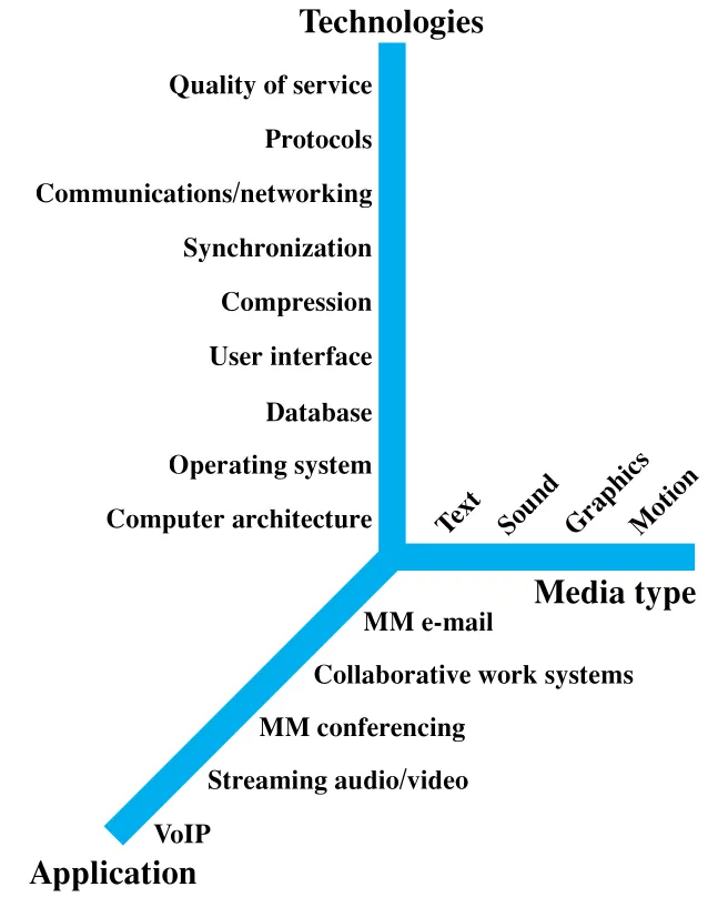 Figure 2.11 · PDF p. 68 · media type, application, supporting technology로 보는 multimedia taxonomy
Media Types
Text는 keyboard로 입력할 수 있고 직접 읽거나 출력할 수 있는 정보다. Text messaging, instant messaging, non-HTML e-mail, chat room, message board가 예다. 더 넓게는 audio/graphics/video에 속하지 않는 file/database data도 text 범주로 다뤄질 수 있다.
Audio는 크게 voice/speech와 music으로 나뉜다. Human speech는 보통 4 kHz 이하의 modest bandwidth로 전송할 수 있어 telephony, voice mail, audio teleconferencing 같은 전통 voice communication application에 쓰인다. Music은 더 넓은 frequency spectrum을 요구한다.
Image service는 개별 picture, chart, drawing의 통신을 지원한다. Facsimile, CAD, publishing, medical imaging이 예다. Image는 drawing program이나 PDF처럼 vector graphics format으로 표현될 수도 있고, pixel의 2차원 배열인 raster graphics format으로 표현될 수도 있다. JPG는 raster graphics 기반의 compressed format이다.
Video는 시간에 따른 picture sequence를 운반한다. 본질적으로 video는 raster-scan image의 sequence를 사용한다.
Multimedia Applications
초기 Internet은 information retrieval, e-mail, file transfer, 그리고 text/image 중심 Web interface가 지배적이었다. 이후 visualization과 real-time interactivity를 지원하기 위해 massive data를 다루는 multimedia application이 늘어났다. 대표 예는 streaming audio/video이고, interactive 예로 distributed simulation과 real-time user interaction이 결합된 virtual training environment가 언급된다.
Multimedia application domain은 information system, communication system, entertainment system, business system, educational system으로 넓게 퍼진다. Hypermedia, multimedia-capable database, content-based retrieval, computer games, digital video, MP3 audio, videoconferencing, shared workspace, virtual community, online training, electronic book, streaming media 등이 예다.
Elastic and Inelastic Traffic
Network traffic은 크게 elastic traffic과 inelastic traffic으로 나눌 수 있다. 이 구분은 multimedia를 지원하려면 Internet architecture가 왜 강화되어야 하는지를 보여준다.
| traffic type | 의미 | 예시와 요구 |
|---|---|---|
Elastic traffic | delay와 throughput 변화에 넓은 범위로 적응하면서 application 요구를 만족할 수 있는 traffic | file transfer, e-mail, remote logon, network management, Web access |
Inelastic traffic | delay와 throughput 변화에 쉽게 적응하지 못하는 traffic | real-time voice/video, delay-sensitive stock trading, teleconferencing |
Elastic traffic도 요구가 모두 같지는 않다. E-mail은 delay 변화에 둔감하지만, online file transfer는 throughput 변화에 민감하다. Network management는 평소 delay가 심각하지 않을 수 있지만, congestion 원인이 failure일 때는 management message가 빠르게 통과해야 한다. Remote logon과 Web access 같은 interactive application은 delay에 민감하다. 그래서 elastic traffic만 고려하더라도 필요에 따라 resource를 다르게 배분하는 service가 유용하다.
Inelastic traffic은 더 까다롭다. Minimum throughput, delay 상한, delay variation 상한, packet loss 허용 범위가 중요하다. Real-time interactive application에서는 delay variation이 커지면 receiver buffer가 커지고 실제 전달 지연도 커진다. Variable queuing delay와 congestion loss가 있는 환경에서 이런 요구를 만족하기 어렵기 때문에, Internet architecture에는 더 demanding한 application에 preferential treatment를 제공하는 수단이 필요하다. 동시에 기존 elastic traffic도 계속 지원해야 한다.
Multimedia Technologies
Multimedia를 지원하는 기술은 communications/networking만이 아니라 computer architecture, operating system, database, user interface, compression, synchronization, protocols, QoS까지 넓다. 이 책의 범위에서 중요한 항목은 다음과 같다.
| 기술 | 역할 |
|---|---|
Compression | digitized video/audio가 만드는 거대한 traffic을 줄임. JPG는 still image, MPG는 video compression의 대표 표준 |
Communications/networking | SONET, ATM 같은 high-volume multimedia traffic 지원 전송·네트워킹 기술 |
Protocols | RTP(Real-time Transport Protocol)는 inelastic traffic 지원, SIP(Session Initiation Protocol)는 IP network 위 real-time session 설정·수정·종료 담당 |
QoS(Quality of Service) | priority, delay constraint, delay variability constraint 등 application traffic별 service level 차등 제공 |
Appendix 2A The Trivial File Transfer Protocol
TFTP(Trivial File Transfer Protocol)는 RFC 1350에 정의된 Internet standard이며, 이 장에서는 protocol의 구성 요소를 보여주는 간결한 예시로 쓰인다. TFTP는 FTP보다 훨씬 단순하다. Access control이나 user identification이 없기 때문에 public access file directory 같은 제한된 용도에 적합하다. 단순한 대신 구현이 작고 쉬워서, diskless device가 boot time에 firmware를 내려받는 용도처럼 쓰일 수 있다.
TFTP는 UDP 위에서 동작한다. Transfer를 시작하는 TFTP entity는 target system의 destination port 69로 RRQ(Read Request) 또는 WRQ(Write Request)를 UDP segment에 담아 보낸다. Port 69는 target UDP module이 이 message를 TFTP module로 넘기게 하는 well-known identifier다. 하지만 transfer가 진행되는 동안에는 각 side가 자기 TID(Transfer Identifier)를 port number로 사용한다.
TFTP Packets
TFTP entity는 command, response, file data를 모두 UDP segment body에 들어가는 packet 형태로 교환한다. 모든 TFTP packet의 처음 2 bytes는 packet type을 식별하는 opcode다. Figure 2.13은 TFTP의 다섯 packet format을 보여준다.
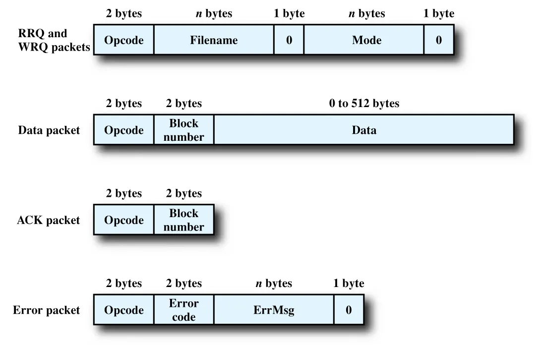 Figure 2.13 · PDF p. 76 · RRQ/WRQ, DATA, ACK, ERROR의 TFTP packet format
| TFTP packet | 역할 | 핵심 필드와 규칙 |
|---|---|---|
RRQ | 상대 system에서 file을 가져오도록 요청 | Filename은 ASCII byte sequence 뒤 0 byte로 종료, mode는 netascii 또는 octet |
WRQ | 상대 system으로 file을 보내도록 요청 | RRQ와 같은 filename/mode 구조를 사용 |
DATA | file data block 전달 | block number는 1부터 시작해 1씩 증가, data는 0-512 bytes |
ACK | DATA packet 또는 WRQ packet 수신 확인 | DATA ACK는 해당 block number 포함, WRQ ACK는 block number 0 |
ERROR | 오류를 알림 | error code와 사람이 읽을 ASCII error message, 0 byte 종료 |
DATA packet의 길이는 transfer 종료를 나타내는 신호이기도 하다. Data field가 정확히 512 bytes이면 마지막 block이 아니다. 0-511 bytes이면 이것이 마지막 data block이며 transfer 종료를 의미한다. 이 규칙 덕분에 별도의 end-of-file packet 없이도 끝을 알 수 있다.
TFTP에서는 duplicate ACK와 termination에 쓰이는 packet을 제외하면 packet들이 acknowledge된다. Error가 없을 때 WRQ 또는 DATA packet은 ACK로 확인된다. RRQ를 보낸 경우 상대가 곧바로 첫 DATA block을 보내며, 이 첫 DATA block이 RRQ에 대한 acknowledgment 역할을 한다. Transfer가 완료되기 전에는 한쪽의 ACK 다음에 다른 쪽의 DATA가 오므로, DATA packet도 앞선 ACK에 대한 응답처럼 동작한다.
Figure 2.14는 TFTP data packet이 UDP와 IP 안에 어떻게 놓이는지 보여준다. TFTP packet이 UDP로 내려가면 UDP header가 붙어 UDP segment가 되고, 이것이 IP로 내려가 IP header가 붙으면 IP datagram이 된다. Chapter 2 앞부분에서 본 encapsulation이 실제 application protocol에 적용된 모습이다.
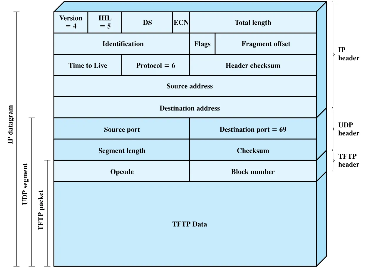 Figure 2.14 · PDF p. 78 · TFTP packet이 UDP segment와 IP datagram 안에 encapsulation된 모습
Overview of a Transfer
Figure 2.15의 예시는 A가 B로 file을 write하는 단순 transfer다. 오류와 option specification은 고려하지 않는다. A의 TFTP module은 file name XXX와 mode octet을 담은 WRQ를 B의 TFTP module에 보낸다. 이 WRQ는 UDP segment body에 들어가며, UDP destination port는 69다. Source port는 A가 선택한 TID, 예시에서는 1511이다.
B가 file 수신을 허용하면 block number 0의 ACK를 보낸다. 이 ACK의 UDP destination port는 1511이므로 A의 UDP entity는 이를 해당 TFTP module로 라우팅할 수 있다. B도 이 transfer를 위한 자기 TID를 source port로 선택하며, 예시에서는 1660이다. 이후 A는 DATA block을 하나씩 보내고 B는 각 block을 ACK한다. 마지막 DATA packet은 512 bytes보다 작은 data를 담아 transfer 종료를 표시한다.
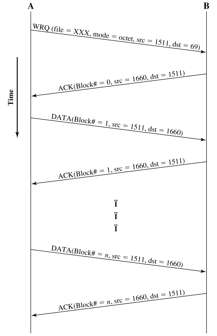 Figure 2.15 · PDF p. 79 · WRQ, ACK, DATA block, ACK가 반복되는 TFTP file transfer 예시
Errors and Delays
TFTP는 UDP 위에서 동작하므로 UDP 자체의 reliable delivery를 기대할 수 없다. Network나 internet 위에서는 packet loss가 가능하므로 TFTP가 자체적으로 lost packet을 처리해야 한다. TFTP는 timeout mechanism을 사용한다. A가 acknowledgment가 필요한 packet을 B에 보내면 timer를 시작한다. Timer가 expire되기 전에 ACK를 받지 못하면 A는 같은 packet을 retransmit한다.
원래 packet이 lost된 경우 retransmission이 B가 받은 첫 copy가 된다. 반대로 원래 packet은 도착했지만 B의 ACK가 lost된 경우, B는 같은 packet을 두 번 받는다. 이때 block number가 있으므로 B는 duplicate를 구분할 수 있고, 둘 다 acknowledge하면 된다. Duplicate ACK는 예외적으로 두 번째 ACK를 무시한다.
Syntax, Semantics, and Timing in TFTP
TFTP는 2.1절의 protocol 세 요소를 깔끔하게 보여준다.
| Protocol feature | TFTP에서의 모습 |
|---|---|
Syntax | RRQ, WRQ, DATA, ACK, ERROR packet format과 opcode/field 배치 |
Semantics | packet type별 의미, error code, block number 규칙, transfer 종료 의미 |
Timing | packet 교환 순서, block number 증가, timeout과 retransmission, ACK/DATA lock-step 진행 |
따라서 TFTP는 기능은 단순하지만 protocol을 공부하기에는 좋은 예시다. Header format, port/TID, packet sequence, timeout, duplicate 처리, UDP 위 application-level reliability가 모두 작은 범위 안에 들어 있다.
연결 관계
- Chapter 1의 communications tasks 중
exchange management,error detection,flow control,addressing,routing이 Chapter 2에서는 protocol layer와 PDU/header 구조로 구체화된다. TCP/IP protocol suite는 이후 Internet Protocol, routing protocol, TCP/UDP, Internet application 장의 기준 구조가 된다.Encapsulation은 이후 모든 packet format 이해의 기본이다. Application data는 TCP segment, IP datagram, network-level packet/frame으로 내려가며 각 layer header를 얻는다.- OSI model은 실제 구현보다 설명과 표준화의 기준틀로 쓰이며, layer boundary와 service definition을 이해하는 데 중요하다.
- Multimedia의
elastic traffic/inelastic traffic,QoS,RTP,SIP는 뒤의 congestion control, integrated/differentiated services, real-time multimedia protocol로 이어진다. - TFTP는 UDP 위에서 application protocol이 직접 reliability를 보강하는 작은 사례이며, transport service 선택이 application 설계에 어떤 영향을 주는지 보여준다.
오해하기 쉬운 내용
Protocol은 단순한 packet format이 아니다.syntax,semantics,timing을 모두 포함한다.- TCP/IP에서
IP address와port는 다른 수준의 주소다. IP address는 host를 찾고, port는 host 안의 process/application을 찾는다. IP는 destination port를 알 필요가 없다. Port는 transport layer의 관심사이고, IP는 destination host로 datagram을 보내는 데 집중한다.UDP는 “오류가 없는 protocol”이 아니라, delivery/order/duplication protection을 보장하지 않는 최소 transport protocol이다. 필요한 reliability는 application이 보강할 수 있다.OSI model이 통신 설명에서 중요하다고 해서 실제 Internet protocol stack이 OSI protocol로 구현된다는 뜻은 아니다. 실제 주류는 TCP/IP다.Service definition은 어떻게 구현할지를 강제하지 않는다. 상위 layer에 무엇을 제공하는지를 정의하고, 내부 구현은 system별 최적화를 허용한다.Multimedia는 여러 media type의 동시 사용만 뜻하지 않는다. VoIP나 streaming audio처럼 단일 media라도 real-time 처리 요구가 있으면 multimedia application으로 다뤄진다.- TFTP에서 마지막 DATA packet은 별도 종료 flag가 아니라 512 bytes보다 작은 data length로 표시된다.
면접 질문
Protocol architecture가 필요한 이유를 file transfer 예시로 설명하라.- Protocol의
syntax,semantics,timing은 각각 무엇이며, TFTP에서는 어떻게 나타나는가? - TCP/IP의 physical, network access, internet, transport, application layer가 각각 맡는 책임은 무엇인가?
TCP segment,IP datagram, network-levelpacket/frame의 관계를 encapsulation 관점에서 설명하라.TCP와UDP의 차이를 reliability, ordering, overhead, application 선택 관점에서 비교하라.- IPv4에서 IPv6로 확장된 가장 큰 동기는 무엇이며, address field 길이는 어떻게 달라지는가?
- OSI 7계층과 TCP/IP 계층은 어떻게 대응되는가?
Protocol specification,Service definition,Addressing/SAP은 layer-specific standard에서 각각 어떤 역할을 하는가?Confirmed service와nonconfirmed service의 primitive sequence 차이는 무엇인가?Elastic traffic과inelastic traffic의 차이를 QoS 요구와 연결해 설명하라.- TFTP가 UDP 위에서 timeout/retransmission과 block number를 사용하는 이유는 무엇인가?