개요
Asynchronous Transfer Mode (ATM), 또는 cell relay는 X.25보다 빠른 packet switching을 위해 현대 digital facility의 높은 신뢰성과 품질을 활용한 streamlined packet transfer interface다. ATM의 핵심은 정보를 고정 크기 packet인 cell로 나누고, 여러 logical connection을 하나의 physical interface 위에 multiplexing하며, error/flow control 기능을 최소화해 고속 처리에 맞춘다는 점이다.
이 장은 보류 주제이므로 특정 표준 필드 암기보다 다음 흐름을 이해하는 데 초점을 둔다.
| 세부 주제 | 핵심 질문 | 대표 용어 |
|---|---|---|
| Protocol architecture | ATM은 어떤 layer와 plane으로 나뉘는가? | ATM layer, AAL, user plane, control plane, management plane |
| ATM logical connections | 왜 VCC만이 아니라 VPC를 두는가? | VCC, VPC, virtual channel, virtual path |
| ATM cells | 왜 fixed-size cell을 쓰는가? | 53-octet cell, header, payload, VPI, VCI, HEC |
| Transmission of ATM cells | cell stream을 어떻게 동기화하고 운반하는가? | HEC, cell delineation, SDH, STM-1 |
| ATM service categories | traffic 유형별 QoS 요구를 어떻게 나누는가? | CBR, rt-VBR, nrt-VBR, UBR, ABR, GFR |
핵심 개념
ATM이 해결하려는 문제
ATM은 Chapter 10의 X.25, frame relay와 같은 계열의 packet transfer 기술이다. 공통점은 data를 discrete chunk로 전송하고, 여러 logical connection을 하나의 physical interface 위에 multiplexing한다는 점이다. 차이는 ATM이 각 logical connection의 information flow를 고정 크기 cell로 조직한다는 점이다.
고정 크기 cell은 두 가지 효과를 노린다.
| 설계 선택 | 효과 |
|---|---|
| fixed-size, fixed-format cell | node에서 cell processing이 단순해져 high data rate에 유리하다. |
| minimal error/flow control | per-cell processing overhead와 overhead bit 수를 줄여 X.25보다 빠른 switching을 지향한다. |
ATM은 link가 자주 오류를 내는 환경보다, optical fiber와 digital transmission처럼 신뢰성이 높은 환경을 전제로 한다. 따라서 hop-by-hop recovery를 두껍게 넣기보다, 고속 switching과 QoS 기반 service category를 제공하는 쪽으로 설계 방향이 이동한다.
세부 정리
11.1 Protocol Architecture
ATM protocol architecture는 user와 network 사이 interface를 설명하는 모델이다. 물리 계층은 transmission medium과 signal encoding scheme을 정의하고, 본문 기준으로 25.6 Mbps부터 622.08 Mbps까지의 data rate가 언급된다. 이 위에 ATM 기능을 담당하는 두 layer가 있다.
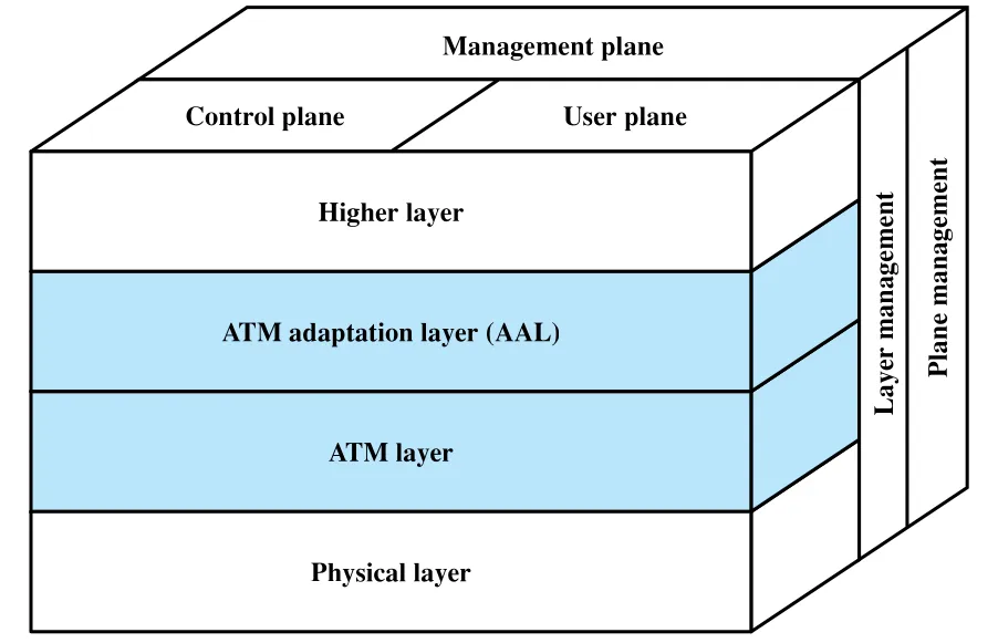 Figure 11.1 · PDF p. 349 · ATM layer, AAL, physical layer와 user/control/management plane 구조
| Layer/Plane | 역할 |
|---|---|
| Physical layer | transmission medium, signal encoding, bit-level transport를 담당한다. |
| ATM layer | 모든 service에 공통인 packet transfer 기능을 제공한다. fixed-size cell 전송과 logical connection 사용을 정의한다. |
| ATM Adaptation Layer (AAL) | ATM 기반이 아닌 higher-layer information을 ATM cell에 맞게 분할/조립한다. service-dependent layer다. |
| User plane | user information transfer와 관련 control을 제공한다. |
| Control plane | call control과 connection control을 담당한다. |
| Management plane | system 전체 조정, plane 간 coordination, layer별 resource/parameter 관리를 담당한다. |
**AAL(ATM Adaptation Layer)**이 필요한 이유는 higher-layer protocol이 처음부터 53-octet ATM cell 단위로 정보를 만들지 않기 때문이다. AAL은 higher-layer information을 ATM network가 운반할 수 있는 cell payload 흐름으로 바꾸고, 수신 측에서는 cell에서 정보를 모아 higher layer로 넘긴다.
11.2 ATM Logical Connections: VCC와 VPC의 출발점
ATM의 logical connection 기본 단위는 **virtual channel connection (VCC)**이다. VCC는 X.25의 virtual circuit과 유사하며, ATM network에서 switching의 기본 단위다. 두 end user 사이에 VCC가 설정되면, 그 connection 위로 fixed-size cell이 variable-rate, full-duplex flow로 교환된다. VCC는 user data뿐 아니라 user-network control signaling, network-network management/routing에도 사용될 수 있다.
ATM은 여기에 **virtual path connection (VPC)**이라는 두 번째 sublayer를 둔다. VPC는 같은 endpoint를 갖는 여러 VCC의 bundle이다. 즉 하나의 VPC 안에 속한 모든 VCC의 cell들은 network 내부에서 같은 묶음으로 함께 switching될 수 있다.
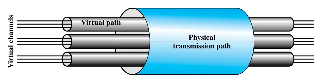 Figure 11.2 · PDF p. 350 · physical transmission path 위에 virtual path와 virtual channel이 계층적으로 놓이는 관계
VPC가 등장한 이유는 high-speed network에서 control cost가 전체 network cost에서 차지하는 비중이 커지기 때문이다. 개별 VCC마다 transit node에서 call processing을 수행하면 고속 transport의 이점을 잃기 쉽다. VPC는 공통 path를 공유하는 여러 connection을 하나의 group으로 다루어 network management action을 개별 connection이 아니라 connection group에 적용하게 한다.
Virtual Path를 쓰는 이유
VPC를 쓰면 network transport function을 두 층으로 나눌 수 있다. 개별 logical connection에 관련된 기능은 virtual channel (VC) 수준에서 다루고, 여러 logical connection의 묶음에 관련된 기능은 virtual path (VP) 수준에서 다룬다.
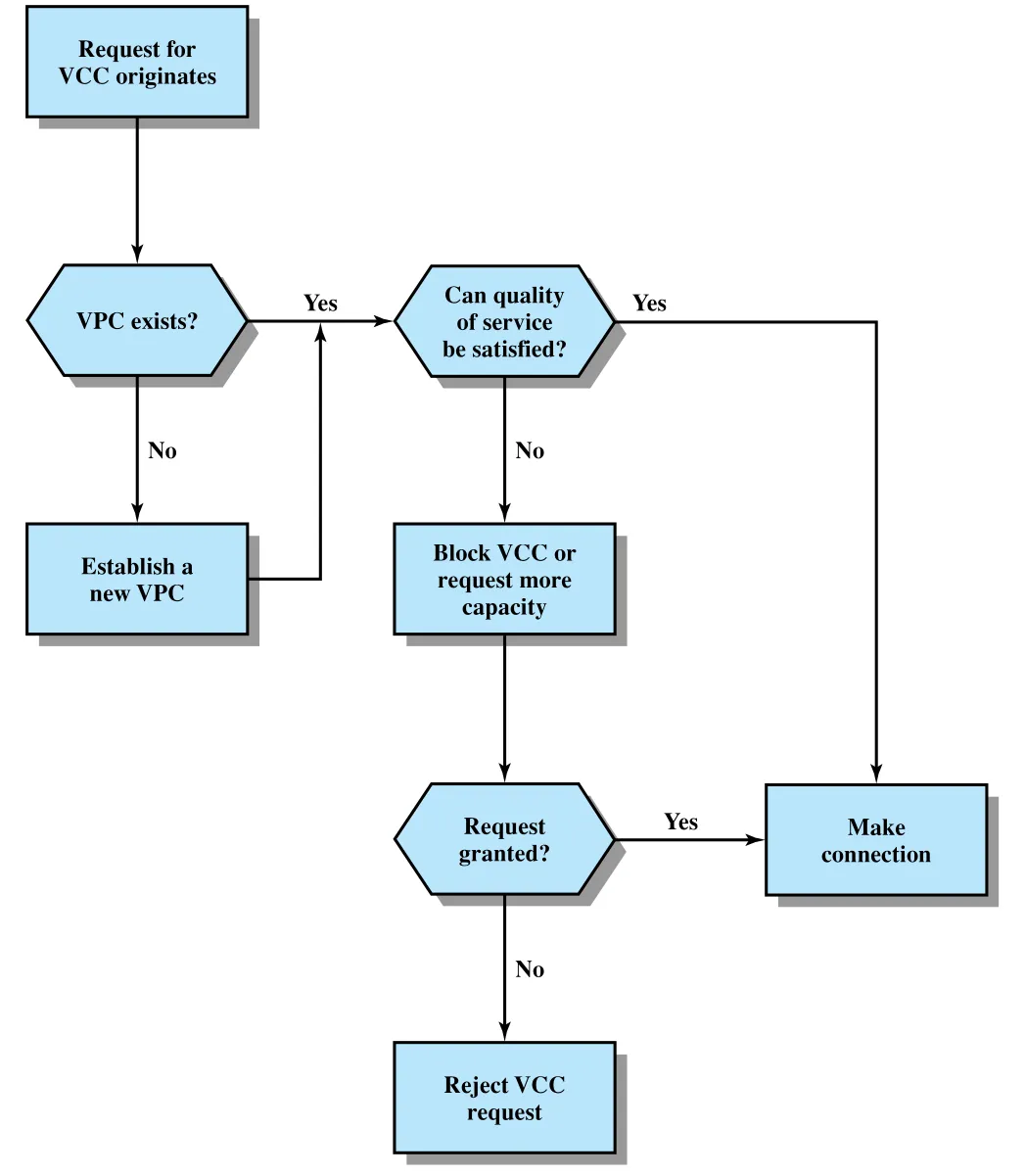 Figure 11.3 · PDF p. 351 · 기존 VPC의 QoS/capacity를 확인해 VCC를 만들거나 새 VPC를 만드는 흐름
Figure 11.3의 흐름은 다음처럼 읽으면 된다.
- VCC request가 발생한다.
- 요구 destination으로 가는 VPC가 이미 있는지 확인한다.
- VPC가 있고 QoS와 capacity가 충분하면 endpoint에서 간단한 state mapping만 저장해 VCC를 만든다.
- VPC가 없으면 새 VPC를 설정해야 한다.
- VPC는 있지만 QoS/capacity가 부족하면 capacity request를 하거나 VCC request를 block/reject한다.
이 구조의 이점은 transit node에서 개별 VCC마다 복잡한 call processing을 반복하지 않아도 된다는 점이다. Virtual path control은 route 계산, capacity allocation, connection state 저장처럼 무거운 작업을 담당한다. 이후 같은 VPC 안에 VCC를 추가할 때는 virtual channel/virtual path mapping 같은 endpoint 중심의 작업만 필요하므로 setup이 빨라진다.
Virtual Path/Virtual Channel Terminology
ATM 표준 용어는 다소 헷갈리므로, 다음처럼 계층을 잡아두면 된다.
| 용어 | 의미 |
|---|---|
| Virtual Channel (VC) | 공통 identifier 값으로 연관된 ATM cell의 unidirectional transport를 가리키는 일반 용어다. |
| Virtual Channel Link | VCI 값이 할당된 지점부터 그 VCI가 변환 또는 종료되는 지점까지의 unidirectional cell transport 구간이다. |
| Virtual Channel Identifier (VCI) | 특정 VPC 안에서 특정 VC link를 식별하는 numerical tag다. |
| Virtual Channel Connection (VCC) | ATM layer service user 사이를 잇는 VC link들의 concatenation이다. 같은 VCC에 속한 cell sequence integrity가 보존된다. |
| Virtual Path (VP) | 공통 identifier 값으로 연관된 여러 virtual channel의 ATM cell transport를 가리키는 일반 용어다. |
| Virtual Path Link | 공통 VPI 값으로 식별되는 VC link 묶음이며, VPI가 할당된 지점부터 변환/종료 지점까지 이어진다. |
| Virtual Path Identifier (VPI) | 특정 VP link를 식별한다. |
| Virtual Path Connection (VPC) | 같은 VPI를 공유하는 VC link bundle의 길이를 따라 이어지는 VP link들의 concatenation이다. |
용어에서 중요한 감각은 VCI는 VPC 안에서 VC를 식별하고, VPI는 VP를 식별한다는 점이다. ATM cell header에는 VPI와 VCI가 함께 들어가며, switch는 이 값을 이용해 cell을 적절한 path/channel로 넘긴다.
VCC/VPC의 사용과 특성
VCC endpoint는 end user일 수도 있고 network entity일 수도 있다. 원문은 세 가지 use case를 든다.
| VCC 사용 | 설명 |
|---|---|
| end user 사이 | end-to-end user data 또는 end user 간 control signaling을 운반한다. |
| end user와 network entity 사이 | user-to-network control signaling에 사용된다. |
| network entity 사이 | network traffic management와 routing function에 사용된다. |
VCC와 VPC에는 공통적으로 다음 특성이 붙는다.
| 특성 | 의미 |
|---|---|
| Quality of service (QoS) | cell loss ratio, cell delay variation 같은 parameter로 service 품질을 표현한다. |
| switched/semipermanent connection | switched VCC/VPC는 on-demand setup/teardown이 필요하고, semipermanent VCC/VPC는 configuration 또는 network management로 장기간 설정된다. |
| cell sequence integrity | 같은 VCC/VPC 안의 cell 순서가 보존된다. |
| traffic parameter negotiation and usage monitoring | average rate, peak rate, burstiness, peak duration 등을 협상하고, network가 위반 여부를 감시한다. |
ATM network는 congestion을 막기 위해 새 VCC request를 거부할 수 있고, negotiated parameter를 위반하거나 congestion이 심하면 cell을 discard할 수 있으며, 극단적으로는 existing connection을 terminate할 수도 있다. VPC에도 QoS와 traffic parameter가 붙는 이유는, VPC가 group 단위 capacity discipline을 제공하고 그 안에서 end user들이 새 VCC를 만들 때 선택 범위를 제한하기 때문이다.
Control Signaling
ATM에서는 VPC/VCC를 만들고 해제하기 위한 control signaling이 필요하며, 이 signaling은 관리 대상인 user-data connection과 별도의 connection에서 수행된다.
VCC establishment/release 방식은 다음처럼 요약된다.
| 방식 | 핵심 |
|---|---|
| Semipermanent VCC | user-to-user exchange에 사용되며 별도 control signaling이 필요 없다. |
| Meta-signaling channel | signaling channel을 만들기 위해 먼저 low-rate permanent channel을 사용한다. |
| User-to-network signaling VCC | meta-signaling channel로 만든 VCC를 call control signaling에 사용하고, 이를 통해 user data VCC를 만든다. |
| User-to-user signaling VCC | preestablished VPC 안에서 end user들이 network intervention 없이 user-to-user VCC를 만들고 해제하는 데 사용한다. |
VPC는 prior agreement로 semipermanent하게 만들 수도 있고, customer가 signaling VCC로 network에 요청할 수도 있으며, network가 자신의 convenience를 위해 network-controlled 방식으로 만들 수도 있다.
11.3 ATM Cells
ATM은 고정 크기 cell을 사용한다. 하나의 ATM cell은 5-octet header와 48-octet information field로 이루어진 53-octet cell이다.
고정 크기 cell의 장점은 다음과 같다.
| 장점 | 설명 |
|---|---|
| 낮은 queueing delay 가능성 | high-priority cell이 lower-priority cell 뒤에 도착해도, 앞 cell이 작기 때문에 기다리는 시간이 줄어든다. |
| hardware switching에 유리 | fixed-size cell은 switch mechanism을 hardware로 구현하기 쉽다. |
| high data rate 지원 | variable-length packet보다 cell processing이 단순해 ATM node가 매우 높은 data rate를 처리하기 쉽다. |
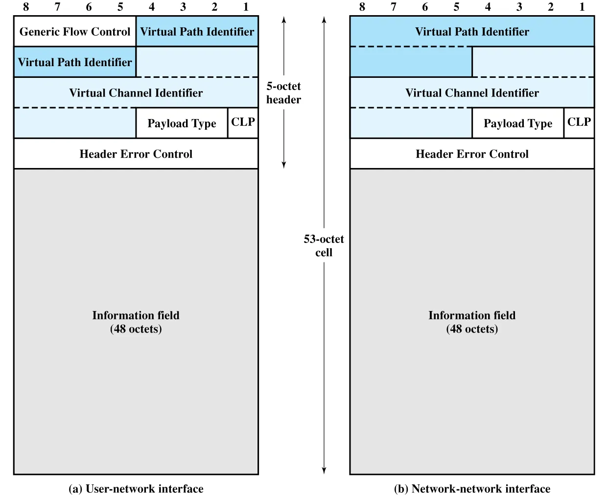 Figure 11.4 · PDF p. 355 · UNI와 NNI에서 ATM cell header가 VPI/VCI/HEC 등을 담는 형식
Figure 11.4는 두 header format을 보여준다. **UNI(User-Network Interface)**에서는 GFC field가 있고, **NNI(Network-Network Interface)**에서는 GFC가 빠진 대신 VPI bit 수가 더 커진다.
| Field | 위치/크기 감각 | 역할 |
|---|---|---|
| GFC(Generic Flow Control) | UNI에만 존재 | local user-network interface에서 short-term overload 완화를 위한 cell flow control에 사용된다. |
| VPI(Virtual Path Identifier) | UNI에서는 8 bits, NNI에서는 12 bits | network routing field로, virtual path를 식별한다. NNI에서 더 많은 VPC를 지원하기 위해 크다. |
| VCI(Virtual Channel Identifier) | header 내부 | end user 방향의 routing과 logical channel 식별에 사용된다. |
| PT(Payload Type) | 3 bits | information field가 user data인지, OAM/resource management cell인지 등을 나타낸다. |
| CLP(Cell Loss Priority) | 1 bit | congestion 시 discard 우선순위를 알려준다. |
| HEC(Header Error Control) | 8 bits | header error detection/correction과 cell synchronization에 사용된다. |
Payload Type (PT)
Payload Type (PT) field는 information field 안의 정보 종류를 알려준다. 첫 bit가 0이면 user information이고, 이때 둘째 bit는 congestion experienced 여부를 나타내며, 셋째 bit는 SDU(Service Data Unit) type을 구분한다. 여기서 SDU는 ATM cell의 48-octet payload를 가리킨다.
첫 bit가 1이면 user data가 아니라 network management 또는 maintenance information을 싣는 cell이다. 이 덕분에 user VCC 위에 management cell을 삽입해도 user data 의미를 깨뜨리지 않고 inband control information을 전달할 수 있다.
Cell Loss Priority (CLP)
CLP(Cell Loss Priority) bit는 congestion이 생겼을 때 어떤 cell을 먼저 버릴지 network에 힌트를 준다.
| CLP 값 | 의미 |
|---|---|
0 | relatively higher priority cell이다. 다른 대안이 없을 때만 discard한다. |
1 | network congestion 시 discard 대상이 되기 쉽다. |
User는 negotiated rate를 초과하는 extra cell에 CLP=1을 붙여 보낼 수 있다. Network가 한 switch에서 traffic agreement 위반을 감지했지만 아직 처리 가능하다고 판단하면, 그 cell의 CLP를 1로 표시해 이후 congestion 지점에서 우선 discard되게 할 수 있다.
Generic Flow Control (GFC)
**GFC(Generic Flow Control)**는 UNI에서 subscriber 쪽에서 network 쪽으로 흐르는 traffic을 제어해 short-term overload를 완화하기 위한 mechanism이다. 모든 connection은 flow control 대상인지 아닌지로 나뉘며, controlled connection은 one-queue model 또는 two-queue model로 그룹화될 수 있다.
세부 bit coding은 표준 암기 성격이 강하므로 핵심만 남기면 다음과 같다.
| 개념 | 의미 |
|---|---|
| HALT/NO_HALT | network side가 subscriber 측 transmission을 멈추거나 재개시키는 신호다. |
| SET/NULL | controlled connection에 보낼 수 있는 credit counter를 채우거나 그대로 둔다. |
| GO_CNTR/GO_VALUE | controlled cell 전송 가능 횟수를 나타내는 credit counter와 초기값이다. |
| one-queue/two-queue model | controlled traffic을 하나 또는 두 그룹(Group A/B)으로 나눠 별도 제어할 수 있다. |
GFC는 ATM 전체 end-to-end flow control이라기보다, local UNI에서 순간 overload를 완화하려는 장치로 이해하는 편이 정확하다.
Header Error Control (HEC)의 위치
각 ATM cell에는 header의 나머지 32 bits를 바탕으로 계산되는 8-bit HEC(Header Error Control) field가 있다. 생성 다항식은 X^8 + X^2 + X + 1로 주어진다. 일반적인 error code는 긴 data에 짧은 code를 붙여 detection을 주로 하지만, ATM header는 입력이 32 bits로 짧고 code가 8 bits라 일부 error pattern에 대해서는 correction도 가능하다. 다음 구간에서 HEC receiver algorithm과 cell delineation을 이어서 본다.
11.4 Transmission of ATM Cells
ATM cell을 전송하려면 두 가지 문제가 생긴다. 첫째, header error를 어떻게 처리할 것인가. 둘째, fixed-size cell이 연속 bit stream으로 올 때 cell boundary를 어떻게 찾을 것인가. ATM은 이 두 문제에 모두 **HEC(Header Error Control)**를 사용한다.
HEC Receiver Operation
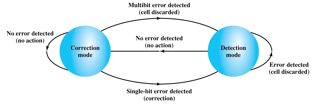 Figure 11.5 · PDF p. 359 · HEC receiver가 correction mode와 detection mode 사이를 오가는 방식
HEC receiver는 기본적으로 single-bit error correction을 시도하는 correction mode에서 시작한다. Cell을 받을 때마다 HEC를 계산해 수신 header의 HEC와 비교한다.
| 상황 | 동작 |
|---|---|
| no error detected | correction mode를 유지하고 cell을 정상 처리한다. |
| single-bit error detected | header error를 correction하고 detection mode로 이동한다. |
| multibit error detected | cell을 discard하고 detection mode로 이동한다. |
| detection mode에서 error detected | correction을 시도하지 않고 cell을 discard한다. |
| detection mode에서 no error detected | 다시 correction mode로 돌아간다. |
왜 error를 한 번 본 뒤 detection mode로 바꾸는가? Burst noise나 다른 event가 연속 오류를 만들 수 있기 때문이다. HEC는 single-bit correction에는 유용하지만 긴 burst error를 고치기에는 충분하지 않다. 따라서 error가 나타난 직후에는 보수적으로 correction을 멈추고 discard 중심으로 동작해, 잘못된 header를 가진 cell이 unintended service로 전달될 확률을 낮춘다.
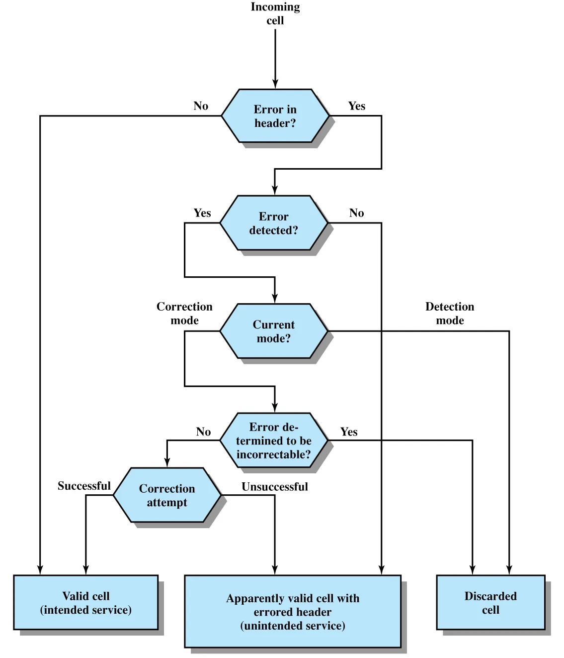 Figure 11.6 · PDF p. 360 · cell header error가 valid cell, errored header cell, discarded cell로 이어지는 경로
Figure 11.6은 HEC가 완벽한 magic이 아니라 trade-off임을 보여준다. Error가 없으면 intended service로 valid cell이 전달된다. Correctable single-bit error라면 correction 후 valid cell이 된다. 그러나 incorrectable error이거나 detection mode에서 error가 잡히면 discarded cell이 된다. 더 나쁜 경우는 error를 놓쳐 apparently valid cell with errored header가 되는 경우인데, HEC 설계는 이 확률을 낮추려 한다.
Cell-Based Physical Layer와 Cell Delineation
I.432는 ATM cell 전송 data rate로 622.08 Mbps, 155.52 Mbps, 51.84 Mbps, 25.6 Mbps 등을 언급한다. Cell을 운반하는 physical layer 방식은 크게 두 가지다.
| 방식 | 핵심 |
|---|---|
| Cell-based physical layer | 외부 framing 없이 53-octet cell이 continuous stream으로 이어진다. |
| SDH-based physical layer | ATM cell stream을 SDH/STM frame 안에 실어 보낸다. |
Cell-based physical layer는 외부 frame이 없기 때문에 synchronization을 cell header의 HEC로 찾아야 한다. 이 과정을 cell delineation이라 한다.
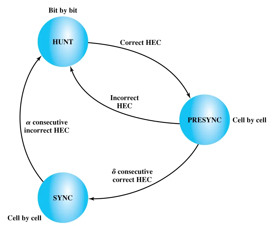 Figure 11.8 · PDF p. 361 · HUNT, PRESYNC, SYNC로 이어지는 cell delineation state diagram
Cell delineation 상태는 다음과 같이 움직인다.
| State | 동작 | 전이 조건 |
|---|---|---|
| HUNT | bit by bit로 HEC coding law가 맞는 위치를 찾는다. | correct HEC match가 나오면 PRESYNC로 간다. |
| PRESYNC | cell structure가 있다고 가정하고 cell by cell로 HEC를 확인한다. | HEC law가 d번 연속 맞으면 SYNC로 간다. |
| SYNC | cell boundary를 알고 있다고 보고 HEC를 error detection/correction에 사용한다. | HEC law가 a번 연속 틀리면 synchronization을 잃었다고 보고 HUNT로 돌아간다. |
여기서 a와 d는 design parameter다. d를 크게 하면 synchronization acquisition이 느려지지만 false delineation에 강해진다. a를 크게 하면 misalignment를 알아차리는 속도는 늦어지지만 false misalignment에 강해진다.
SDH-Based Physical Layer
SDH-based physical layer는 ATM cell stream 위에 외부 frame structure를 부여한다. 본문은 155.52 Mbps에서 STM-1(STS-3) frame을 예로 든다.
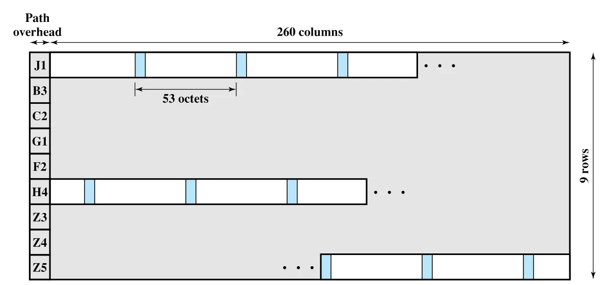 Figure 11.11 · PDF p. 363 · STM-1 payload 안에 ATM cells가 실리고 cell boundary가 payload boundary를 넘을 수 있는 구조
STM-1 payload는 path overhead 9 octets와 ATM cell을 담는 나머지 영역으로 구성된다. Payload capacity는 2340 octets인데, 이는 cell length 53 octets의 정수배가 아니다. 따라서 ATM cell은 STM-1 payload boundary를 가로질러 이어질 수 있다. 이때 path overhead의 H4 octet은 H4 이후 첫 cell boundary까지 몇 octet이 남았는지를 나타내며, 값 범위는 0-52다.
SDH-based approach의 장점은 다음과 같다.
| 장점 | 설명 |
|---|---|
| ATM/STM payload 모두 수용 | 고용량 fiber infrastructure를 circuit-switched/dedicated application에 먼저 쓰다가 ATM 지원으로 migration할 수 있다. |
| 특정 connection의 circuit switching 가능 | 예를 들어 constant-bit-rate video traffic을 독점 payload envelope에 map해 circuit switched 방식으로 처리할 수 있다. |
| synchronous multiplexing | 여러 ATM stream을 합쳐 더 높은 bit rate interface를 만들 수 있다. 예: 155 Mbps STM-1 네 개를 622 Mbps STM-4로 결합. |
Cell-based 방식은 transmission과 transfer mode가 공통 cell structure를 써 interface가 단순하다는 장점이 있고, SDH-based 방식은 기존 synchronous infrastructure와 migration 측면에서 유리하다.
11.5 ATM Service Categories
ATM network는 voice, video, bursty TCP flow처럼 서로 다른 traffic을 동시에 운반하도록 설계되었다. 모든 flow는 VCC 위를 지나는 53-octet cell stream이지만, application이 요구하는 delay, jitter, loss, rate 특성은 다르다. 그래서 end system은 필요한 service type을 ATM service category로 식별한다.
가장 중요한 구분은 real-time과 non-real-time이다. Real-time application은 원래 source의 audio/video flow를 사용자에게 연속적으로 재현해야 하므로 delay와 delay variation, 즉 jitter에 민감하다. Non-real-time application은 bursty traffic이 많고 delay/jitter 제약이 상대적으로 느슨해 network가 statistical multiplexing을 더 적극적으로 활용할 수 있다.
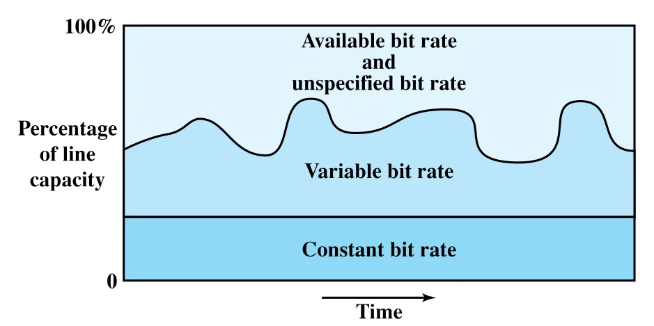 Figure 11.12 · PDF p. 366 · line capacity가 CBR, VBR, ABR/UBR 계층으로 배분되는 ATM bit rate service 개념
ATM service categories는 다음처럼 정리된다.
| Category | Real-time 여부 | Traffic 성격 | Network 약속/동작 | 대표 예 |
|---|---|---|---|---|
| CBR(Constant Bit Rate) | real-time | fixed data rate가 connection lifetime 동안 계속 필요 | relatively tight upper bound on transfer delay, 지속 capacity 제공 | uncompressed audio/video, telephony, videoconferencing |
| rt-VBR(real-time Variable Bit Rate) | real-time | time-sensitive이지만 rate가 시간에 따라 변함 | delay와 delay variation을 tight하게 제한하면서 statistical multiplexing 활용 | compressed real-time video |
| nrt-VBR(non-real-time Variable Bit Rate) | non-real-time | bursty이나 traffic flow를 어느 정도 characterize 가능 | peak cell rate, sustainable/average cell rate, burstiness 정보를 기반으로 낮은 delay/loss QoS 제공 | airline reservation, banking transaction, process monitoring |
| UBR(Unspecified Bit Rate) | non-real-time | delay/loss를 어느 정도 견딜 수 있는 traffic | 남는 capacity를 FIFO로 사용, congestion feedback 없음, best-effort | TCP-based data/image transfer, messaging, remote terminal |
| ABR(Available Bit Rate) | non-real-time | bursty source이지만 공정한 capacity sharing이 필요 | PCR과 MCR을 지정하고, unused capacity를 explicit feedback으로 fair하게 공유 | LAN interconnection, router over ATM |
| GFR(Guaranteed Frame Rate) | non-real-time | frame-based traffic, 특히 IP/Ethernet over ATM | minimum capacity를 보장하고, congestion 시 frame boundary를 고려해 cell들을 묶어 discard | IP backbone subnetwork, LAN-router-ATM backbone |
Real-Time Services: CBR과 rt-VBR
**CBR(Constant Bit Rate)**는 정의가 가장 단순하다. Connection lifetime 동안 fixed data rate가 계속 필요하고 transfer delay의 upper bound가 비교적 빡빡한 application에 사용된다. Uncompressed audio/video처럼 source rate가 거의 일정하고 delay/jitter에 민감한 traffic에 맞다.
**rt-VBR(real-time Variable Bit Rate)**은 delay와 delay variation 제약은 CBR처럼 엄격하지만, source rate가 시간에 따라 달라지는 application을 위한 category다. 압축 video는 frame마다 size가 달라질 수 있지만 frame presentation은 일정한 pace로 이루어져야 하므로 rt-VBR에 어울린다. CBR보다 network가 여러 connection을 같은 dedicated capacity 위에 statistical multiplexing할 여지가 크다.
Non-Real-Time Services: nrt-VBR, UBR, ABR, GFR
**nrt-VBR(non-real-time Variable Bit Rate)**은 real-time은 아니지만 loss/delay QoS를 어느 정도 보장받고 싶은 bursty application에 사용된다. End system은 peak cell rate, sustainable/average cell rate, burstiness, peak duration 같은 traffic parameter를 제시하고, network는 이를 바탕으로 resource를 할당한다.
**UBR(Unspecified Bit Rate)**은 CBR/VBR traffic이 쓰고 남은 capacity를 best-effort로 사용하는 category다. FIFO로 cell을 forwarding하고, initial commitment도 congestion feedback도 제공하지 않는다. TCP-based traffic처럼 variable delay와 일부 cell loss를 upper layer가 감당할 수 있는 경우에 적합하다.
**ABR(Available Bit Rate)**은 UBR로는 부족한 bursty source를 위해 만들어졌다. Application은 사용할 **PCR(Peak Cell Rate)**과 필요한 **MCR(Minimum Cell Rate)**을 지정한다. Network는 모든 ABR source가 최소 MCR을 받도록 하고, 남는 capacity는 explicit feedback으로 fair and controlled하게 나눈다. ABR이 쓰지 않는 capacity는 UBR traffic이 사용할 수 있다.
**GFR(Guaranteed Frame Rate)**은 IP backbone subnetwork와 frame-based traffic을 지원하기 위해 추가된 category다. UBR보다 나은 service를 제공하되 ABR보다 router 간 구현 부담을 낮추는 방향이다. 핵심은 network element가 frame/packet boundary를 인식해 congestion 때문에 cell을 버려야 할 때 한 frame을 구성하는 cell들을 함께 discard하도록 하는 것이다. 또한 GFR VC마다 minimum capacity를 reserve할 수 있고, network가 congested가 아니면 추가 frame도 보낼 수 있다.
연결 관계
| 연결 대상 | 이어지는 이유 |
|---|---|
| Chapter 10 X.25/frame relay | ATM은 X.25처럼 logical connection을 쓰고 frame relay처럼 streamlined transfer를 지향하지만, fixed-size cell과 service category/QoS를 더 강하게 전면에 둔다. |
| Chapter 8 SDH/SONET | SDH-based physical layer와 STM-1/STM-4 multiplexing은 synchronous TDM infrastructure 위에서 ATM cell을 운반하는 방식이다. |
| Chapter 12 Routing | VPC/VCC 설정과 network-to-network management/routing traffic은 switched network routing과 연결된다. |
| Chapter 13 Congestion Control | CLP, ABR feedback, GFR discard behavior, service category별 resource allocation은 ATM traffic management로 이어진다. |
| TCP/IP traffic | UBR, ABR, GFR은 TCP/IP 및 Ethernet/LAN traffic을 ATM backbone 위에 싣는 문제와 연결된다. |
오해하기 쉬운 내용
| 오해 | 바로잡기 |
|---|---|
| ATM은 그냥 packet switching이다 | packet switching 계열이지만 fixed-size 53-octet cell, VPC/VCC, service category 중심 QoS가 핵심 차이다. |
| VPC는 VCC와 같은 말이다 | VCC는 switching의 기본 logical connection이고, VPC는 같은 endpoint/path를 공유하는 VCC bundle이다. |
| VPC가 있으면 capacity 문제가 사라진다 | 기존 VPC의 QoS/capacity가 부족하면 capacity request가 필요하거나 VCC가 reject/block될 수 있다. |
| HEC는 cell 전체 오류를 고친다 | HEC는 header 32 bits에 대한 8-bit control field이며, header error detection/correction과 cell delineation에 쓰인다. |
| GFC는 end-to-end flow control이다 | GFC는 UNI에서 local short-term overload 완화를 위한 flow control이다. |
| CLP=1 cell은 항상 버려진다 | congestion이 없으면 전달될 수 있지만, congestion 시 우선 discard 대상이 된다. |
| Cell-based transmission은 frame synchronization이 필요 없다 | 외부 frame은 없지만 HEC 기반 cell delineation으로 cell boundary synchronization을 잡아야 한다. |
| UBR과 ABR은 같은 best-effort다 | UBR은 commitment/feedback이 없는 best-effort이고, ABR은 MCR 보장과 explicit feedback 기반 fair sharing을 제공한다. |
핵심 용어
Asynchronous Transfer Mode (ATM), cell relay, ATM cell, fixed-size cell, 53-octet cell, 5-octet header, 48-octet information field, ATM layer, ATM Adaptation Layer (AAL), physical layer, user plane, control plane, management plane, virtual channel (VC), virtual channel connection (VCC), virtual channel link, Virtual Channel Identifier (VCI), virtual path (VP), virtual path connection (VPC), virtual path link, Virtual Path Identifier (VPI), Quality of Service (QoS), cell loss ratio, cell delay variation, control signaling, meta-signaling channel, UNI(User-Network Interface), NNI(Network-Network Interface), Generic Flow Control (GFC), Payload Type (PT), Service Data Unit (SDU), Cell Loss Priority (CLP), Header Error Control (HEC), cell delineation, HUNT, PRESYNC, SYNC, SDH, STM-1, STS-3, H4 octet, CBR(Constant Bit Rate), rt-VBR(real-time Variable Bit Rate), nrt-VBR(non-real-time Variable Bit Rate), UBR(Unspecified Bit Rate), ABR(Available Bit Rate), GFR(Guaranteed Frame Rate), PCR(Peak Cell Rate), MCR(Minimum Cell Rate), jitter.
면접 질문
- ATM이 X.25와 frame relay에 비해 fixed-size cell을 사용하는 이유는 무엇인가?
- ATM protocol architecture에서 ATM layer와 AAL(ATM Adaptation Layer)의 역할 차이는 무엇인가?
- User plane, control plane, management plane은 각각 무엇을 담당하는가?
- VCC와 VPC의 차이를 설명하고, VPC가 high-speed network의 control cost를 줄이는 이유를 말해 보라.
- VPI와 VCI가 ATM cell forwarding에서 각각 어떤 역할을 하는가?
- ATM cell이 5-octet header와 48-octet payload로 구성된다는 사실이 switching delay와 hardware implementation에 어떤 의미를 갖는가?
- UNI와 NNI의 ATM cell header 차이는 무엇인가?
- PT, CLP, HEC field의 역할을 각각 설명하라.
- HEC receiver가 correction mode와 detection mode를 오가는 이유는 무엇인가?
- Cell delineation에서 HUNT, PRESYNC, SYNC state는 각각 무엇을 의미하는가?
- Cell-based physical layer와 SDH-based physical layer의 차이는 무엇인가?
- CBR, rt-VBR, nrt-VBR, UBR, ABR, GFR을 traffic 특성과 QoS 보장 관점에서 비교하라.