개요
Congestion control은 packet-switching network, frame relay, ATM network, IP-based internetwork에서 공통으로 등장하는 핵심 설계 문제다. Congestion은 network 안에서 전달 중인 packet 수가 network의 packet-handling capacity에 가까워지면서 queueing delay, buffer overflow, retransmission, control overhead가 함께 커지는 상태다. 이 장의 목표는 network 안의 packet 수를 성능이 급격히 무너지기 전 수준으로 유지하는 방법을 이해하는 것이다.
이 장에서 packet이라는 말은 넓게 쓴다. Packet-switching network의 packet, frame relay의 frame, ATM의 cell, Internet의 IP datagram을 모두 포함한다. 따라서 핵심 질문은 “하나의 packet format을 어떻게 다루는가”가 아니라 “여러 node와 queue로 이루어진 network가 load 증가에 어떻게 반응하고, 이를 어떤 mechanism으로 제한하는가”다.
| 세부 주제 | 핵심 질문 | 대표 용어 |
|---|---|---|
| Effects of Congestion | load가 capacity에 가까워질 때 throughput과 delay는 왜 무너지는가? | queueing, buffer overflow, offered load, normalized throughput |
| Congestion Control | congestion을 줄이기 위해 어떤 feedback/control 구조를 쓸 수 있는가? | backpressure, choke packet, implicit signaling, explicit signaling |
| Traffic Management | 예방 중심의 traffic policy는 무엇을 관리하는가? | discard policy, flow control, admission control, traffic shaping |
| Packet-Switching / Frame Relay | flow control이 약한 switched network에서 congestion을 어떻게 알리고 제한하는가? | FECN, BECN, DE bit, CIR, committed burst size |
| ATM Traffic Management | traffic contract를 기준으로 cell flow를 어떻게 감시하고 조정하는가? | QoS, CBR, VBR, UBR, ABR, GFR, PCR, SCR, MCR, CDV |
| ATM-GFR Traffic Management | frame 단위의 TCP/IP traffic을 ATM에서 어떻게 더 공정하게 처리하는가? | GFR, CLP, tagging, buffering, scheduling |
핵심 개념
Congestion은 queue가 연결된 network 현상이다
Data network나 internetwork는 본질적으로 network of queues다. 각 switch/router node에는 outgoing channel마다 packet queue가 있고, packet arrival rate가 packet transmission rate보다 크면 queue size가 계속 증가한다. Arrival rate가 transmission rate보다 조금 낮더라도, utilization이 높아질수록 queue length와 delay가 급격히 커진다. 원문은 practical rule of thumb으로 line utilization이 약 80%를 넘으면 queue length가 위험하게 증가한다고 설명한다.
혼잡이 어려운 이유는 단일 node의 buffer 문제로 끝나지 않기 때문이다. 어떤 output queue가 막히면 그 queue로 packet을 보내려는 upstream node의 output buffer도 차기 시작하고, 이것이 인접 node들로 전파된다. 결국 congestion은 local overflow가 아니라 network region 또는 전체 network의 throughput collapse로 이어질 수 있다.
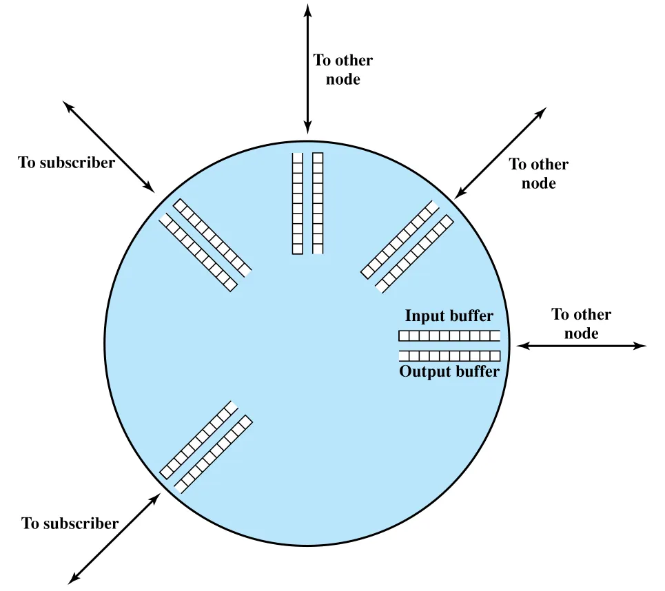 Figure 13.1 · PDF p. 399 · node의 input buffer와 output buffer 구조
Figure 13.1은 switch/router의 각 I/O port가 input buffer와 output buffer를 가진다는 직관을 보여준다. Packet은 port로 들어와 input buffer에 저장되고, node가 routing decision을 한 뒤 적절한 output buffer로 이동한다. Output queue는 가능한 빠르게 link로 전송되는데, 여러 source의 packet이 같은 outgoing link를 공유하므로 결과적으로 statistical time division multiplexing처럼 동작한다.
Buffer 구성은 고정 크기의 per-port buffer일 수도 있고, 모든 port가 공유하는 memory pool일 수도 있다. 어느 쪽이든 전체 buffer resource는 유한하다. Packet이 node의 processing rate보다 빠르게 들어오거나 outgoing buffer가 비워지는 속도보다 빠르게 쌓이면, 결국 새 packet을 받을 memory가 없어진다. 이때 node는 packet을 discard하거나, neighbor에게 flow를 줄이도록 pressure를 걸어야 한다.
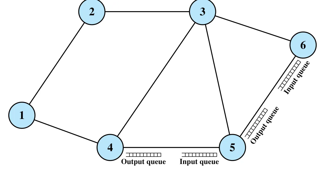 Figure 13.2 · PDF p. 399 · 한 node의 congestion이 인접 node queue로 전파되는 구조
Figure 13.2는 flow control이 강력하지만 조심스럽게 써야 하는 이유를 보여준다. Node 6이 node 5에서 오는 packet을 억제하면 node 5의 output queue가 차고, node 5를 향해 보내던 다른 node들도 영향을 받는다. 그래서 congestion control은 단순히 “막힌 node 앞에서 packet을 세운다”가 아니라, network 전체의 traffic distribution과 queue interaction을 관리하는 문제다.
Ideal Performance: throughput은 포화되고 delay는 무한대로 간다
Congestion control의 이상적인 목표는 Figure 13.3처럼 표현된다. Offered load는 source end system들이 network에 넣는 packet 양이고, throughput은 destination end system에 실제로 전달된 packet 양이다. 둘 다 network의 theoretical maximum throughput으로 normalize하면, 이상적인 network에서는 offered load가 capacity에 도달할 때까지 throughput이 같이 증가하고, 그 이후에는 normalized throughput이 1.0으로 유지된다.
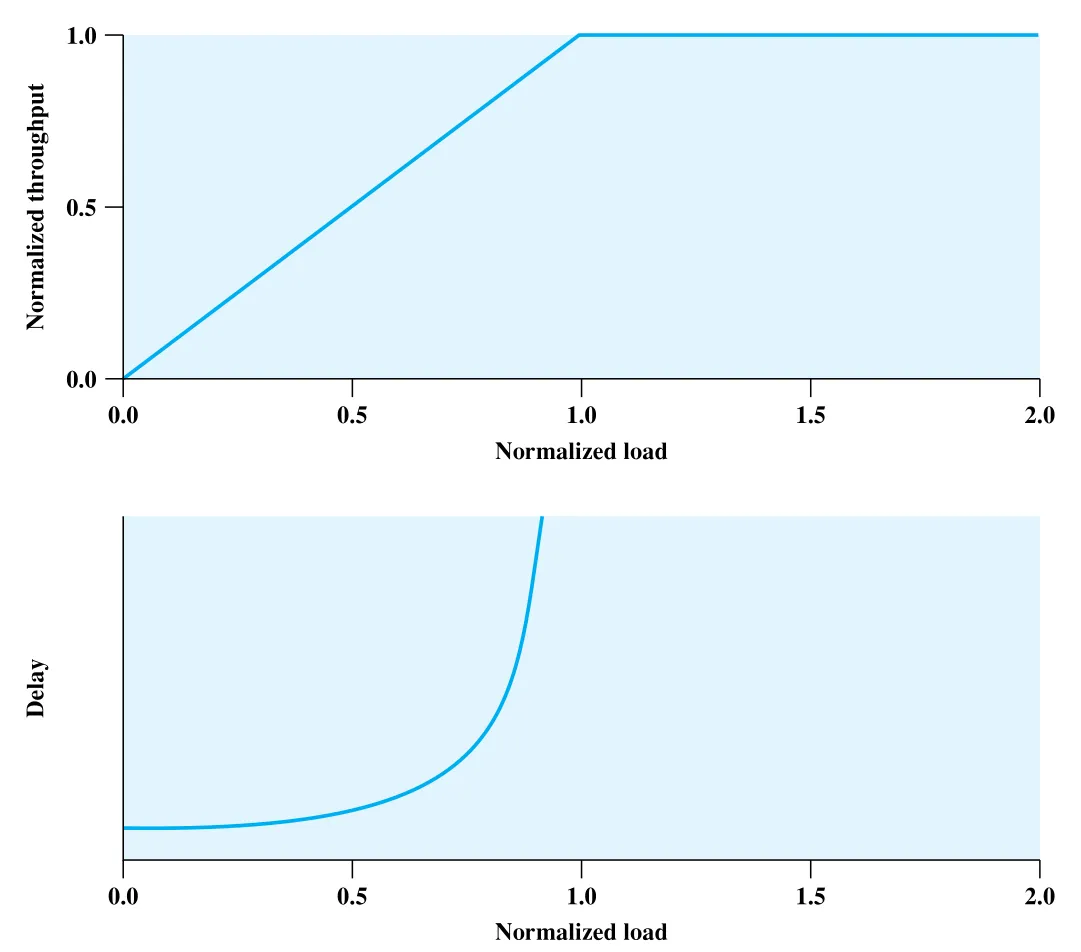 Figure 13.3 · PDF p. 400 · ideal network utilization에서 throughput과 delay의 관계
하지만 throughput이 1.0으로 유지되는 이상적인 경우에도 delay는 다른 문제다. Light load에서는 propagation delay와 node processing delay만 있어 end-to-end delay가 작다. Load가 증가하면 각 node의 queueing delay가 더해진다. Offered load가 capacity를 넘으면 network로 들어오는 packet rate가 나가는 packet rate보다 크므로, infinite buffer를 가정해도 internal queue size는 계속 증가한다. 따라서 steady state에서 queueing delay는 bounded value로 수렴하지 않고 무한대로 증가한다.
이 그림은 달성 가능한 성능이 아니라 upper bound에 가깝다. 어떤 congestion control scheme도 Figure 13.3보다 더 좋은 성능을 낼 수는 없다. 현실의 control mechanism은 buffer finite성, control message overhead, retransmission overhead 때문에 이 이상선 아래에서 움직인다.
Practical Performance: moderate congestion에서 severe congestion으로
현실에서는 buffer가 finite하고 congestion을 제어하려는 signaling도 capacity를 소비한다. 아무 제어 없이 offered load를 계속 올리면 Figure 13.4와 같은 collapse가 나타난다.
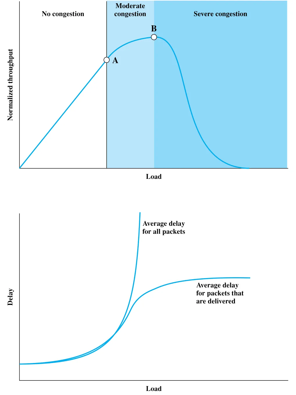 Figure 13.4 · PDF p. 402 · offered load 증가에 따른 moderate congestion과 severe congestion
Figure 13.4의 point A 이전은 no congestion에 가깝다. Offered load가 늘면 throughput도 거의 같이 증가한다. Point A 이후에는 moderate congestion에 들어간다. Network가 아직 traffic을 처리할 수는 있지만, throughput 증가율이 offered load 증가율보다 낮아지고 delay가 빠르게 커진다.
이 구간에서 ideal curve를 벗어나는 이유는 여러 가지다.
| 원인 | 의미 |
|---|---|
| uneven load distribution | traffic이 network 전체에 균등하게 퍼지지 않아 일부 node는 이미 severe congestion을 겪을 수 있다. |
| packet discard | 특정 queue가 saturated되면 packet을 버리고, 이는 later retransmission load를 만든다. |
| adaptive routing overhead | congestion이 낮은 route를 찾기 위해 routing message 교환이 늘어나 data packet에 쓸 capacity가 줄어든다. |
Point B 이후는 severe congestion이다. Node buffer가 가득 차 packet discard가 늘고, source는 discarded packet을 retransmit한다. 더 나쁜 점은 성공적으로 전달된 packet조차 higher layer에서 ACK가 너무 늦게 도착하면 lost packet으로 오인되어 retransmission될 수 있다는 것이다. 그러면 new packet과 old packet retransmission이 함께 network에 들어와 load를 더 키우고, effective capacity는 0에 가까워진다. 이 현상이 congestion collapse의 핵심이다.
Delay 그래프도 중요하다. 모든 packet의 average delay는 discard된 packet까지 포함하기 때문에 load가 심해질수록 계속 커진다. 반면 delivered packet만 놓고 본 average delay는 severe congestion에서 다른 양상을 보일 수 있다. 너무 오래 queue에 머무는 packet은 결국 discard되고, 운 좋게 빨리 통과한 packet만 delivered set에 남기 때문이다. 이 지표 착시는 “전달된 packet의 delay가 괜찮아 보인다”는 이유만으로 network가 건강하다고 판단하면 안 된다는 경고다.
세부 정리
13.1 Effects of Congestion
Congestion의 직접 효과는 queue length 증가, queueing delay 증가, buffer overflow, packet discard다. 그러나 network layer와 transport layer가 맞물리면 효과가 증폭된다. Discard된 packet은 source 또는 higher layer에서 retransmission되고, delayed ACK로 인한 timeout도 불필요한 retransmission을 만든다. 따라서 offered load가 조금 늘어난 것처럼 보여도 실제 internal load는 new traffic + retransmitted traffic + control overhead의 합으로 증가한다.
이 절의 핵심은 다음처럼 정리할 수 있다.
| 개념 | 핵심 내용 |
|---|---|
| packet-handling capacity | node processing, outgoing link transmission, buffer availability가 함께 결정한다. |
| queueing delay | utilization이 높아질수록 비선형적으로 증가하며, capacity 초과 시 unbounded growth가 된다. |
| buffer overflow | finite buffer 때문에 packet discard가 발생하고 retransmission pressure를 만든다. |
| propagation of congestion | 한 node의 flow control이 upstream output queue를 채우면서 congestion을 주변으로 전파할 수 있다. |
| ideal vs practical performance | ideal은 throughput upper bound를 보여주지만, practical network는 discard와 overhead 때문에 throughput collapse를 겪는다. |
13.2 Congestion Control
Congestion control mechanism은 크게 보아 network가 congestion을 감지하고 source traffic을 줄이게 만드는 방법들이다. Figure 13.5는 이 장과 뒤 장들에서 나오는 mechanism을 한 장으로 묶는다.
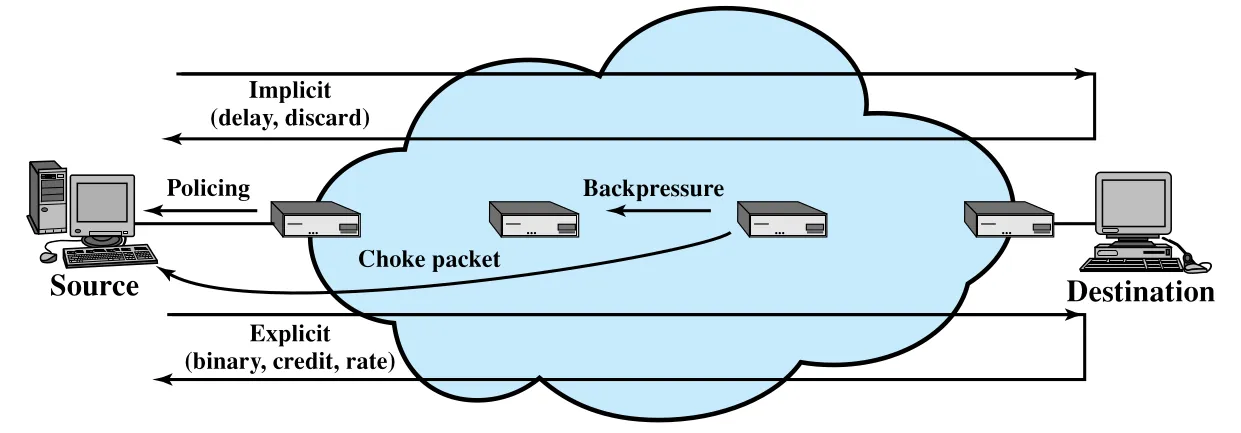 Figure 13.5 · PDF p. 403 · implicit/explicit signaling, policing, backpressure, choke packet의 위치
Backpressure
Backpressure는 congested node가 upstream node의 packet flow를 줄이거나 멈추게 만드는 hop-by-hop 방식이다. 물리적으로 막힌 파이프의 압력이 원점 쪽으로 전파되는 것처럼, node 6의 buffer가 차면 node 6은 node 5나 node 3에서 오는 packet을 제한하고, node 5의 output queue가 차면 node 5도 더 upstream node를 제한한다. 결국 flow restriction이 data traffic의 반대 방향으로 source까지 전파된다.
Backpressure는 link 단위 또는 logical connection, 예를 들어 virtual circuit 단위로 적용할 수 있다. Selective backpressure를 쓰면 모든 traffic을 막는 대신 traffic이 많은 connection만 제한할 수 있다.
하지만 backpressure의 적용 범위는 제한적이다.
| Network 유형 | Backpressure 적용성 |
|---|---|
| X.25-based packet-switching | hop-by-hop flow control을 제공하므로 backpressure가 잘 맞는다. |
| frame relay | hop-by-hop flow restriction capability가 없어 직접적인 backpressure가 어렵다. |
| ATM | frame relay와 마찬가지로 hop-by-hop flow control이 기본 구조에 없다. |
| IP-based internetwork | 전통적으로 router 간 built-in hop-by-hop regulation이 없고, 주로 end-to-end TCP가 반응한다. |
Choke Packet
Choke packet은 congested node가 source node로 보내는 control packet이다. Source에게 “특정 destination으로 보내는 traffic rate를 줄이라”고 요청한다. 대표 예시는 ICMP Source Quench packet이다. Router나 destination end system이 full buffer 때문에 IP datagram을 discard해야 할 때 source quench를 보낼 수 있고, buffer가 capacity에 가까워지는 것을 미리 보고 congestion을 anticipatory하게 알릴 수도 있다.
주의할 점은 source quench message가 해당 datagram의 delivery 여부를 보장하지 않는다는 것이다. Message가 discard된 datagram에 대해 보내질 수도 있고, 아직 전달될 datagram에 대해 미리 보내질 수도 있다. 그래서 choke packet은 비교적 coarse-grained control이다. 더 정교한 방식은 explicit congestion signaling에서 다룬다.
Implicit Congestion Signaling
Implicit congestion signaling은 network node가 명시적으로 congestion bit/control packet을 보내지 않아도, end system이 congestion의 징후를 관찰해 traffic을 줄이는 방식이다. Source가 관찰할 수 있는 대표 증거는 두 가지다.
| Implicit evidence | 해석 |
|---|---|
| increased transmission delay | propagation delay와 processing delay만으로 설명하기 어려운 extra queueing delay가 생겼다. |
| packet discard / loss | finite buffer overflow 또는 congestion-related discard가 발생했다. |
이 방식은 connectionless/datagram environment에 특히 잘 맞는다. Datagram packet-switching network나 IP-based internet에는 network 내부 logical connection이 없기 때문에 node별로 connection flow를 직접 조절하기 어렵다. 대신 TCP connection은 end-to-end ACK와 loss/delay detection을 통해 source rate를 조절한다. 원문은 TCP congestion control을 Chapter 20과 연결한다.
Connection-oriented network에서도 implicit signaling이 가능하다. 예를 들어 frame relay의 end-to-end LAPF control protocol은 TCP와 유사하게 lost frame을 감지하고 flow를 조절할 수 있다.
Explicit Congestion Signaling
Explicit congestion signaling은 network가 growing congestion을 end system에게 직접 알려 주고, end system이 offered load를 줄이도록 만드는 방식이다. 목적은 available capacity를 최대한 쓰되 congestion에 controlled, fair manner로 반응하는 것이다.
Signal 방향은 두 가지다.
| 방향 | 의미 | 전달 방식 |
|---|---|---|
| Backward signaling | congestion을 만날 수 있는 source 쪽 traffic을 줄이라고 source 방향으로 알린다. | source로 향하는 data packet header bit 수정, 또는 별도 control packet |
| Forward signaling | 이 packet/connection이 congested resource를 지났음을 destination 방향으로 알린다. | destination 쪽 packet header bit 수정, 또는 control packet; 일부 scheme은 destination이 echo back |
Explicit signaling은 다시 세 범주로 나뉜다.
| 범주 | 동작 방식 | 특징 |
|---|---|---|
| Binary | congested node가 data packet 안의 bit를 set한다. | source는 congestion indication을 보고 traffic flow를 줄일 수 있다. |
| Credit based | source에게 보낼 수 있는 octet/packet 수를 credit으로 준다. | credit이 소진되면 새 credit 전까지 전송을 멈춘다. End-to-end flow control에 흔하지만 congestion control에도 고려된다. |
| Rate based | source에게 explicit data rate limit을 준다. | connection path의 어느 node든 control message로 source의 allowed rate를 낮출 수 있다. |
13.3 Traffic Management
Traffic management는 congestion이 이미 생겼을 때의 반응뿐 아니라, traffic class와 network policy를 고려해 congestion control을 더 정교하게 적용하는 영역이다. 단순히 saturated node가 last-in-first-discarded 같은 규칙으로 packet을 버리는 것보다, fairness, quality of service, reservation, policing을 함께 고려해야 한다.
Fairness
Congestion이 생기면 source-destination flow마다 delay와 loss가 증가한다. 별도 요구사항이 없다면 여러 flow가 congestion의 고통을 비슷하게 나누는 것이 바람직하다. 단순히 가장 최근에 도착한 packet을 버리는 정책은 특정 high-volume flow가 buffer를 많이 차지하게 둘 수 있어 fair하지 않을 수 있다.
Fairness를 개선하는 한 방법은 node가 logical connection별 또는 source-destination pair별로 separate queue를 유지하는 것이다. 각 queue buffer 길이가 같다면 traffic load가 높은 queue가 더 자주 discard를 겪고, low-traffic connection도 capacity share를 확보할 수 있다.
Quality of Service
Traffic flow는 요구사항이 다르다. Voice/video는 delay sensitive지만 어느 정도 loss에는 견딜 수 있다. File transfer/electronic mail은 delay에는 덜 민감하지만 loss에는 민감하다. Interactive graphics/interactive computing은 delay와 loss 모두에 민감할 수 있다. Network management traffic은 congestion이나 failure 상황에서 application traffic보다 우선순위가 높아야 할 수도 있다.
따라서 congestion 기간에는 서로 다른 flow에 서로 다른 **Quality of Service (QoS)**를 제공해야 한다. 예를 들어 node는 같은 queue 안에서 high-priority packet을 먼저 보낼 수 있고, QoS level별 separate queue를 두어 higher level queue에 preferential treatment를 줄 수도 있다.
Reservations와 Traffic Policing
Reservation scheme은 congestion을 피하고 application에 assured service를 제공하기 위해 connection setup 시 resource를 예약하는 방식이다. ATM network에서는 logical connection을 설정할 때 user와 network가 traffic contract를 맺는다. Contract에는 data rate와 traffic flow characteristic이 들어가고, network는 traffic이 contract parameter 안에 있을 때 defined QoS를 제공한다.
Traffic이 contract를 초과하면 network는 excess traffic을 discard하거나, best-effort로 처리하되 discard 대상이 되게 할 수 있다. 현재 outstanding reservation 때문에 새 reservation에 필요한 resource가 부족하면 connection request를 거절한다. IP-based internetwork에서도 비슷한 아이디어가 RSVP로 발전한다.
Reservation의 한 측면이 traffic policing이다. 보통 end system이 붙는 edge node가 incoming traffic flow를 감시해 traffic contract와 비교한다. Contract를 초과하는 traffic은 즉시 discard하거나, 나중에 discard/delay될 수 있음을 나타내도록 mark한다.
13.4 Congestion Control in Packet-Switching Networks
Packet-switching network에서 시도된 congestion control mechanism은 다음처럼 정리된다.
| Mechanism | 동작 | Trade-off |
|---|---|---|
| Control packet / choke packet | congested node가 일부 또는 모든 source node에 control packet을 보내 transmission rate를 낮춘다. | congestion 기간에 추가 traffic을 만든다. |
| Routing information 활용 | ARPANET처럼 link delay 정보를 routing decision에 반영하고, 이를 source packet generation rate에도 활용한다. | delay가 routing decision에 의해 다시 바뀌므로 congestion control input으로 쓰기에는 너무 빠르게 흔들릴 수 있다. |
| End-to-end probe packet | timestamped probe packet으로 endpoint 사이 delay를 측정한다. | measurement traffic 자체가 overhead다. |
| Packet에 congestion information 추가 | 지나가는 packet header에 congestion indication을 넣는다. Backward 또는 forward 방향으로 알릴 수 있다. | destination이 source에게 다시 알려야 하거나, source가 reverse packet/ACK에서 신호를 받아야 한다. |
이 절은 이후 frame relay와 ATM의 signaling을 이해하는 다리 역할을 한다. 핵심 설계 선택은 “congested node가 source에게 직접 말할 것인가”, “destination을 거쳐 source에게 돌아가게 할 것인가”, “network node가 명시적으로 알려 줄 것인가”, “end system이 loss/delay로 추론하게 둘 것인가”다.
13.5 Frame Relay Congestion Control
Frame relay는 throughput과 efficiency를 높이기 위해 protocol 기능을 streamline한 network다. 그 대가로 frame handler, 즉 frame-switching node는 HDLC류 sliding-window flow control처럼 subscriber나 adjacent frame handler에서 오는 frame flow를 hop-by-hop으로 직접 제어하기 어렵다. 따라서 congestion control은 network와 end user의 공동 책임이 된다.
Frame relay congestion control의 목표는 ITU-T I.370 기준으로 다음 방향을 가진다.
| 목표 | 의미 |
|---|---|
| minimize frame discard | congestion이 있어도 frame loss를 줄인다. |
| maintain agreed QoS | 약속된 quality of service를 높은 확률과 낮은 variance로 유지한다. |
| prevent monopolization | 한 end user가 network resource를 독점하지 못하게 한다. |
| low overhead | 구현이 단순하고 end user/network 양쪽 overhead가 작아야 한다. |
| fair resource distribution | end user 사이에 resource를 공정하게 나눈다. |
| limit congestion spread | congestion이 다른 network나 element로 퍼지는 것을 제한한다. |
| direction-independent operation | 양방향 traffic flow와 관계없이 효과적으로 동작해야 한다. |
Frame Relay Congestion Control Techniques
Table 13.1의 네 기법은 frame relay에서 congestion을 다루는 역할을 구분한다.
| Technique | Type | Function | Key element |
|---|---|---|---|
| Discard control | Discard strategy | network가 어떤 frame을 discard할지 결정하도록 guidance를 제공한다. | DE bit |
| Backward Explicit Congestion Notification | Congestion avoidance | network congestion을 end system에게 알려 반대 방향 traffic 조절을 유도한다. | BECN bit 또는 CLLM message |
| Forward Explicit Congestion Notification | Congestion avoidance | 현재 frame 방향의 congestion 경험을 end system에게 알린다. | FECN bit |
| Implicit congestion notification | Congestion recovery | higher-layer PDU의 sequence number 등을 통해 frame loss를 추론한다. | sequence numbers |
Congestion avoidance는 Figure 13.4의 point A 근처, 즉 severe congestion으로 가기 전에 시작되어야 한다. 이 단계에서는 end user가 loss 같은 뚜렷한 증거를 보기 어렵기 때문에 explicit signaling이 필요하다. 반대로 congestion recovery는 point B 부근이나 severe congestion 영역에서 동작한다. 이미 frame drop이 발생하고, LAPF control protocol이나 TCP 같은 higher layer가 loss를 보고 implicit하게 congestion을 감지한다.
Traffic Rate Management: CIR, DE bit, Bc, Be
Frame relay network는 congestion이 심하면 결국 frame을 discard해야 한다. 단순 arbitrary discard는 사용자가 restraint를 보일 이유를 없애므로, 모든 end system이 가능한 한 빨리 보내는 전략을 택하게 만들고 congestion을 악화시킨다. 이를 피하기 위해 frame relay bearer service는 **Committed Information Rate (CIR)**를 둔다.
CIR은 특정 frame-mode connection에 대해 network가 지원하기로 한 bit/s 단위 rate다. CIR을 초과한 traffic은 congestion 시 discard될 가능성이 높다. 단, committed라는 말이 절대 보장을 뜻하지는 않는다. Extreme congestion에서는 CIR 안의 traffic도 모두 보장되지 않을 수 있다. 그래도 discard가 필요할 때 network는 CIR을 초과한 connection의 frame을 먼저 discard하도록 설계한다.
Node와 access channel 관점에서 CIR 합은 다음 제약을 만족해야 한다.
여기서 는 user access channel 위 connection 의 committed information rate이고, 는 user-network interface의 fixed data-rate TDM channel rate다. 실제로는 node capacity 때문에 일부 CIR을 더 낮게 잡을 수도 있다.
Permanent frame relay connection에서는 CIR이 connection agreement 시점에 정해지고, switched connection에서는 call control protocol의 setup phase에서 협상된다.
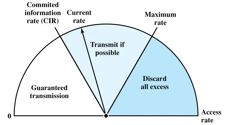 Figure 13.6 · PDF p. 410 · CIR 아래 traffic, excess traffic, maximum rate 초과 discard 영역
Figure 13.6의 metering function은 user station이 붙은 entry frame handler에서 수행된다.
| Traffic 상태 | Frame handler 동작 |
|---|---|
| rate < CIR | incoming frame의 DE bit를 바꾸지 않는다. Guaranteed transmission 영역으로 취급한다. |
| CIR 초과, maximum rate 이하 | 초과 frame의 DE bit를 set하고 forward한다. Congestion이 없으면 전달될 수 있지만 discard 후보가 된다. |
| maximum rate 초과 | entry frame handler에서 excess frame을 discard한다. |
CIR만으로는 bursty traffic을 충분히 표현하기 어렵기 때문에 두 burst parameter가 추가된다.
| Parameter | 의미 |
|---|---|
| Committed burst size (Bc) | measurement interval 동안 network가 정상 조건에서 transfer하기로 동의한 최대 data amount |
| Excess burst size (Be) | 를 초과하지만 network가 정상 조건에서 transfer를 시도할 수 있는 최대 excess data amount. Delivery commitment는 낮다. |
와 의 관계는 다음과 같다.
즉 은 committed data를 시간으로 나눈 rate이고, 는 interval 동안 허용되는 committed data 양이다.
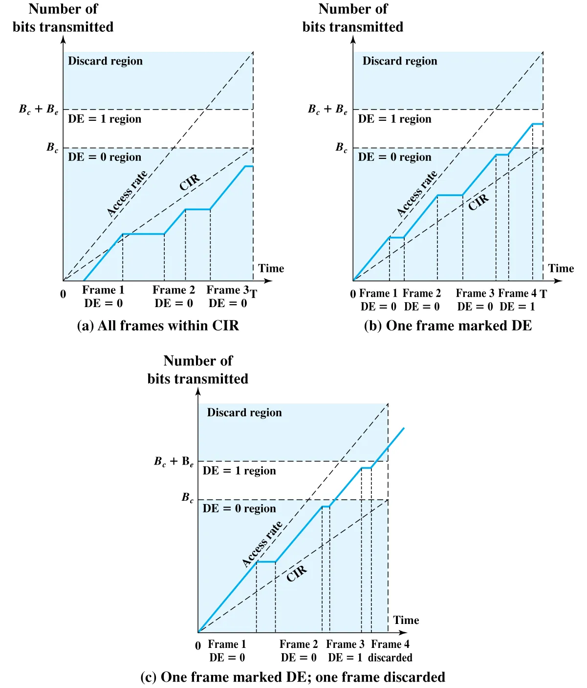 Figure 13.7 · PDF p. 411 · Bc, Be, DE=0/DE=1/discard region의 관계
Figure 13.7은 cumulative bits 기준으로 DE marking과 discard를 보여준다.
| 경우 | 해석 |
|---|---|
| Figure 13.7a | interval 안의 cumulative bits가 이하이므로 모든 frame이 이다. 개별 frame 전송 순간에는 access rate로 보내져 CIR보다 빠를 수 있지만, interval 전체 cumulative amount가 기준이다. |
| Figure 13.7b | 마지막 frame 때문에 cumulative bits가 를 넘으므로 해당 frame은 로 mark된다. |
| Figure 13.7c | 세 번째 frame은 를 넘어 이 되고, 네 번째 frame은 를 넘어 discard된다. |
Explicit Signaling: FECN과 BECN
Frame relay의 explicit congestion avoidance는 available capacity를 최대한 쓰면서도 growing congestion에 controlled, fair manner로 반응하기 위한 구조다. 표준화 과정에서는 두 관점이 있었다. 하나는 congestion이 느리게 발생하고 주로 egress node에서 생긴다는 관점이고, 다른 하나는 internal node에서 매우 빠르게 congestion이 커질 수 있어 빠른 조치가 필요하다는 관점이다. 이 차이가 forward와 backward explicit congestion avoidance에 반영된다.
Frame relay frame의 address field에는 congestion signaling을 위한 두 bit가 있다. 어떤 frame handler든 congestion을 감지하면 bit를 set할 수 있고, 이미 set된 bit는 downstream frame handler가 clear하면 안 된다.
| Bit | 의미 | Source 조절 방식 |
|---|---|---|
| BECN (Backward Explicit Congestion Notification) | 받은 frame의 반대 방향 traffic이 congested resource를 만날 수 있음을 알린다. | user가 바로 자기 전송 rate를 낮추면 된다. |
| FECN (Forward Explicit Congestion Notification) | 이 frame이 같은 방향으로 congested resource를 지났음을 알린다. | receiver가 peer/source에게 higher layer로 flow restriction을 알려야 한다. |
Network response는 각 frame handler가 queueing behavior를 모니터링하는 것에서 시작한다. Queue length가 위험하게 증가하면 FECN, BECN 또는 둘 다 set한다. Early congestion에서는 traffic을 많이 생성하는 logical connection만 notify할 수 있고, serious congestion에서는 해당 handler를 지나는 모든 logical connection에 notification할 수 있다.
User response는 BECN이 단순하고 FECN이 복잡하다. BECN을 받으면 user는 signal이 사라질 때까지 frame transmission rate를 낮추면 된다. FECN은 receiver 쪽에서 source peer에게 “너의 방향 traffic을 줄이라”고 알려야 하므로 core frame relay function만으로는 부족하다. 이 알림은 transport layer, LAPF control protocol, 또는 frame relay sublayer 위의 link control protocol에서 처리될 수 있다.
13.6 ATM Traffic Management
ATM network는 high speed와 small fixed-size cell 때문에 기존 packet-switching/frame relay보다 congestion control이 어렵다. Cell은 빠르게 주입되고, header/control overhead bit는 제한되어 있으며, traffic type도 voice, video, data처럼 다양하다. ATM traffic management는 단순히 loss가 났을 때 source를 늦추는 문제가 아니라, connection setup 단계의 traffic contract, cell-level policing, service category별 QoS 보장을 함께 설계하는 문제다.
ATM에서 기존 congestion control이 잘 안 맞는 이유
ATM traffic과 전송 특성은 전통적인 non-real-time data network와 다르다. Packet-switching이나 frame relay에서는 traffic이 bursty이고 receiver도 bursty arrival을 어느 정도 기대한다. 그래서 simple statistical multiplexing으로 여러 logical connection을 physical interface 위에 묶을 수 있다. 평균 data rate 합이 burst rate 합보다 작기 때문에 UNI capacity도 평균 rate 합보다 조금 큰 수준으로 설계할 수 있다.
ATM에서는 이 접근이 부족하다. 원문이 드는 이유는 다음과 같다.
| 이유 | 설명 |
|---|---|
| traffic이 flow control에 잘 반응하지 않음 | voice/video source는 network가 congested라고 해서 cell 생성을 멈추기 어렵다. |
| feedback이 느림 | cell transmission time이 propagation delay보다 매우 작아, feedback 도착 전 이미 많은 cell이 주입된다. |
| rate 범위가 넓음 | kbps부터 수백 Mbps까지 application capacity 요구가 크게 달라 단순 control이 한쪽을 불리하게 만든다. |
| traffic pattern 다양성 | constant bit rate source와 variable bit rate source를 같은 규칙으로 공정하게 다루기 어렵다. |
| service requirement 다양성 | voice/video는 delay-sensitive, data는 loss-sensitive인 식으로 network service 요구가 다르다. |
| high-speed volatility | 반응형 routing/flow control에 크게 의존하면 극단적이고 낭비적인 fluctuation이 생길 수 있다. |
Latency/Speed Effects
ATM WAN에서 implicit congestion control이 왜 늦는지는 숫자로 드러난다. 150 Mbps에서 ATM cell 하나를 network에 넣는 시간은 대략 다음과 같다.
미국 동서 해안 정도의 거리에서 round-trip propagation delay를 약 로 보면, congestion 때문에 cell drop이 발생하고 destination이 reject message를 보낸 뒤 source가 그 신호를 받기까지 source는 추가로 다음 개수의 cell을 보낼 수 있다.
이는 약 다. 즉 source가 congestion indication에 반응하기 전에 7 Mbit 이상이 이미 network로 들어간다. 그래서 traditional network에서 괜찮던 loss 기반 implicit reaction은 ATM WAN에서는 너무 늦다.
Cell Delay Variation과 CBR Reassembly
ATM은 voice/video를 digitized cell stream으로 전달할 수 있다. 특히 voice는 delay가 짧아야 할 뿐 아니라, destination application에 cell이 constant rate로 전달되어야 한다. Network 내부와 source UNI의 처리 때문에 cell arrival interval에는 variation이 생기므로, destination은 buffer를 두고 일정한 rate로 재조립한다.
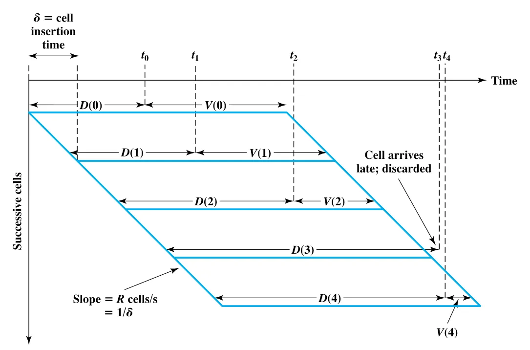 Figure 13.8 · PDF p. 415 · CBR cell stream을 일정 rate로 재조립하기 위한 delay buffer
Figure 13.8에서 는 번째 cell의 end-to-end delay이고, 는 destination이 application에 넘기기 전 추가로 기다리는 reassembly delay다. 첫 cell이 에 도착하면 destination은 만큼 기다린 뒤 application에 전달한다. 이후 cell들은 cells/s의 constant rate로 전달되어야 하므로 delivery interval은 이다.
원문 식을 개념적으로 정리하면 다음과 같다.
또는 이전 cell 기준으로는 다음과 같다.
만약 계산된 가 음수라면, 해당 cell은 약속된 playback/reassembly 시점보다 늦게 도착한 것이므로 discard된다. 따라서 higher layer는 constant bit rate로 data를 받지만, 늦은 cell 때문에 gap이 생길 수 있다. 를 크게 잡으면 late discard가 줄지만 average delay가 늘고, 를 작게 잡으면 delay는 줄지만 cell delay variation에 취약해진다. 이 trade-off 때문에 subscriber는 network provider에게 작은 **Cell Delay Variation (CDV)**를 요구하게 된다.
Network와 UNI가 만드는 Cell Delay Variation
ATM 내부 network contribution은 packet-switching보다 작다. ATM cell은 fixed size이고 header format도 고정이며, intermediate switch에서 flow control/error control 처리를 하지 않도록 설계되었다. 또한 ATM switch는 high throughput을 위해 cell processing time이 매우 작다. 따라서 network 내부에서 눈에 띄는 CDV를 만드는 주된 요인은 congestion이다. Congestion이 생기면 switch queueing delay가 쌓이거나 cell discard가 발생한다.
Source UNI에서도 CDV가 생긴다. Application이 constant bit rate로 data를 만들더라도 AAL, ATM layer, physical layer를 통과하면서 interleaving과 overhead가 발생한다.
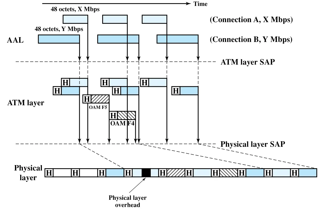 Figure 13.9 · PDF p. 417 · AAL segmentation, ATM cell interleaving, physical overhead가 만드는 CDV
Figure 13.9의 흐름은 다음과 같다.
| 계층 | CDV 원인 |
|---|---|
| AAL | connection별 user data rate가 다르면 48-octet block을 생성하는 시간이 서로 다르다. |
| ATM layer | 여러 connection의 53-octet cell을 physical layer로 interleave해야 하며, 겹치면 한 cell이 기다린다. OAM F4/F5 cell도 user cell 사이에 끼어든다. |
| Physical layer | SDH frame overhead 같은 physical layer overhead bit가 삽입되어 ATM layer bit transmission을 지연시킨다. |
이 지연들은 세부적으로 예측하기 어렵고 반복 패턴도 없으므로, AAL에서 받은 data가 UNI를 넘어 cell로 전송되기까지의 interval에는 random component가 생긴다.
ATM Traffic and Congestion Control Framework
I.371의 ATM layer traffic/congestion control 목표는 세 가지로 압축된다. 첫째, 앞으로 예상되는 network service를 수용할 수 있을 만큼의 ATM layer QoS class를 지원해야 한다. 둘째, network service/application에 특화된 AAL protocol이나 higher-layer protocol에 의존하지 않아야 한다. 셋째, network와 end-system complexity를 줄이면서 network utilization을 높여야 한다.
이를 위해 ITU-T와 ATM Forum은 response time scale에 따라 traffic control function과 congestion control function을 나눈다. Table 13.2를 재구성하면 다음과 같다.
| Response time | Traffic control functions | Congestion control functions |
|---|---|---|
| Long term | Resource management using virtual paths | - |
| Connection duration | Connection Admission Control (CAC) | - |
| Round-trip propagation time | Fast resource management indication | Explicit Forward Congestion Indication (EFCI), ABR flow control |
| Cell insertion time | Usage Parameter Control (UPC), priority control, traffic shaping | selective cell discard |
ATM traffic strategy의 핵심은 새 ATM connection을 받아들일 수 있는지 판단하고, subscriber와 지원할 performance parameter를 합의하는 것이다. 이 합의가 traffic contract다. Network는 특정 performance level을 제공하고, subscriber는 traffic parameter limit을 넘지 않기로 한다. Traffic control은 이 parameter를 설정하고 강제하여 congestion avoidance를 수행한다. Traffic control이 실패해 실제 congestion이 생기면 congestion control function이 recovery를 담당한다.
Resource Management Using Virtual Paths
ATM의 network resource management는 service characteristic이 비슷한 traffic flow를 묶고, 그 묶음에 resource를 배정하는 방식이다. ATM Forum에서 정의한 구체 기능은 Virtual Path Connection (VPC) 사용이다. VPC는 여러 **Virtual Channel Connection (VCC)**를 묶는 단위이며, network는 virtual path에 aggregate capacity와 performance characteristic을 제공하고 내부 VCC들이 이를 공유한다.
VPC 적용 형태는 세 가지다.
| 적용 형태 | VPC 범위 | QoS 책임 |
|---|---|---|
| User-to-user application | 두 UNI 사이 | network는 VPC 내부 VCC별 QoS를 모른다. User가 aggregate demand를 VPC에 맞춰야 한다. |
| User-to-network application | UNI와 network node 사이 | network가 VPC 내부 VCC QoS를 알고 수용해야 한다. |
| Network-to-network application | 두 network node 사이 | network가 VPC 내부 VCC QoS를 알고 수용해야 한다. |
Network resource management에서 중요한 QoS parameter는 Cell Loss Ratio (CLR), Cell Transfer Delay (CTD), **Cell Delay Variation (CDV)**다. 이들은 network가 VPC에 얼마나 많은 resource를 배정하는지에 영향을 받는다. 하나의 VCC가 여러 VPC를 지나면, 해당 VCC의 performance는 각 VPC performance와 VCC-related function을 수행하는 switch/concentrator/node의 처리 방식에 의해 결정된다.
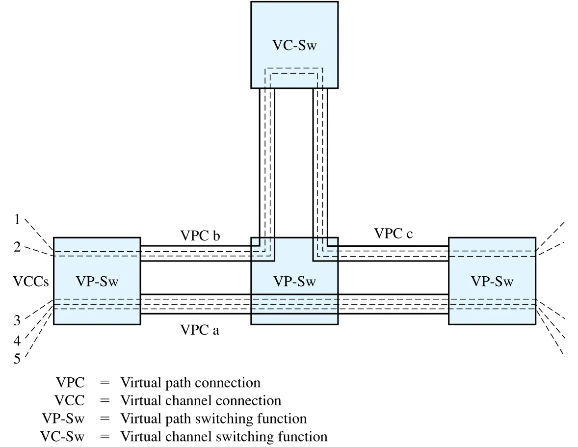 Figure 13.10 · PDF p. 420 · VPC와 VCC의 grouping 및 VP-Sw/VC-Sw 처리 위치
Figure 13.10에서 VCC 1, 2는 VPC b와 VPC c, 그리고 중간 node의 VCC handling 성능에 영향을 받는다. VCC 3, 4, 5는 VPC a를 공유하므로 다른 performance를 경험할 수 있다.
VPC capacity allocation에는 두 선택지가 있다.
| 방식 | 설명 | 장점 | 단점 |
|---|---|---|---|
| Aggregate peak demand | VPC capacity를 내부 모든 VCC의 peak data rate 합과 같게 둔다. | 각 VCC의 peak demand를 수용하는 QoS 제공이 쉽다. | 대부분 시간에 capacity가 underutilized된다. |
| Statistical multiplexing | VPC capacity를 평균 data rate 합 이상, peak demand 합 미만으로 둔다. | capacity utilization이 좋다. | cell delay variation, cell transfer delay, cell loss ratio가 커질 수 있다. |
Statistical multiplexing을 쓸 때는 traffic characteristic과 QoS requirement가 비슷한 VCC를 같은 VPC에 묶는 것이 좋다. 서로 다른 요구의 VCC를 한 VPC에 섞으면 high-demand stream과 low-demand stream 사이의 fair access를 보장하기 어렵다.
Connection Admission Control (CAC)
**Connection Admission Control (CAC)**은 network가 excessive load로부터 자신을 보호하는 첫 방어선이다. User가 새 VPC 또는 VCC를 요청하면, 양방향 traffic characteristic을 implicit 또는 explicit하게 지정해야 한다. 보통 user는 network가 제공하는 QoS class 중 하나를 선택해 traffic characteristic을 표현한다.
Network는 새 connection을 받아들여도 기존 connection들의 agreed QoS를 유지하면서 필요한 resource를 commit할 수 있을 때만 accept한다. Accept되는 순간 network와 user 사이에 traffic contract가 형성되고, user가 contract를 지키는 동안 network는 agreed QoS를 제공한다.
Traffic contract는 Table 13.3의 네 parameter로 구성될 수 있다.
| Parameter | Description | Traffic type |
|---|---|---|
| Peak Cell Rate (PCR) | ATM connection에 submit될 수 있는 traffic의 upper bound | CBR, VBR |
| Cell Delay Variation (CDV) | peak cell rate 기준으로 단일 measurement point에서 관찰되는 cell arrival pattern variability의 upper bound | CBR, VBR |
| Sustainable Cell Rate (SCR) | connection duration 전체에서 계산되는 ATM connection average rate의 upper bound | VBR |
| Burst Tolerance | sustainable cell rate 기준으로 단일 measurement point에서 관찰되는 cell arrival pattern variability의 upper bound | VBR |
CBR source에는 보통 PCR과 CDV가 relevant하고, VBR source에는 네 parameter가 모두 쓰일 수 있다. PCR은 source가 cell을 만들 수 있는 maximum rate지만, Figure 13.9의 UNI CDV 때문에 cell이 clump될 수 있다. 따라서 network가 resource를 제대로 배정하려면 PCR뿐 아니라 CDV도 알아야 한다.
SCR과 Burst Tolerance는 VBR source의 average behavior를 더 자세히 설명한다. 여러 VCC가 하나의 VPC 위에서 statistical multiplexing될 때, peak와 average cell rate를 함께 알면 network가 buffer를 적절히 배정해 resource를 더 효율적으로 사용할 수 있다.
Traffic parameter 값은 Table 13.4처럼 설정될 수 있다.
| Connection type | Connection setup time에 명시 | Subscription time에 지정 | Default rule 사용 |
|---|---|---|---|
| SVC (Switched Virtual Connection) | user/NMS가 signaling으로 요청 | network operator가 subscription별 assign | network-operator default rules |
| PVC (Permanent Virtual Connection) | NMS로 설정 | network operator가 subscription별 assign | network-operator default rules |
또 다른 QoS 요소는 **Cell Loss Priority (CLP)**다. User는 ATM connection에 두 수준의 cell loss priority를 요청할 수 있고, 각 cell의 priority는 cell header의 CLP bit로 표시된다. 두 priority level을 쓰면 보통 high-priority traffic에 대한 parameter set과 aggregate traffic에 대한 parameter set을 따로 지정한다.
Usage Parameter Control (UPC)
Connection이 CAC를 통과한 뒤에는 network의 **Usage Parameter Control (UPC)**가 해당 connection traffic이 traffic contract를 지키는지 감시한다. UPC의 목적은 한 connection의 overload가 다른 connection의 QoS를 망치지 않도록 network resource를 보호하는 것이다. UPC는 VPC level과 VCC level 모두에서 수행될 수 있지만, resource가 보통 virtual path 기준으로 먼저 배정되기 때문에 VPC-level control이 특히 중요하다.
UPC가 감시하는 기능은 두 가지다.
| UPC function | Parameter |
|---|---|
| peak cell rate와 associated CDV 제어 | PCR, CDV tolerance |
| sustainable cell rate와 associated burst tolerance 제어 | SCR, Burst tolerance |
Peak cell rate algorithm은 peak cell rate 과 CDV tolerance limit 를 사용한다. CDV가 없다면 cell interarrival time은 이다. CDV가 있으면 는 peak rate에서의 average interarrival time이며, algorithm은 cell arrival rate를 감시해 interarrival time이 너무 짧아져 tolerance를 넘는 peak rate violation을 만들지 않도록 compliance를 판단한다. 같은 algorithm은 parameter만 바꿔 sustainable cell rate 와 burst tolerance 감시에도 쓰일 수 있다.
UPC algorithm 자체는 compliance를 판단하는 도구다. 실제 action은 network policy가 결정한다.
| Cell 상태 | 단순 UPC action |
|---|---|
| compliant cell | forward/pass |
| noncompliant cell | UPC point에서 discard |
| noncompliant cell with tagging option | 로 tag한 뒤 pass, 이후 congestion 시 discard 후보 |
두 수준의 CLP traffic contract가 있으면 규칙은 더 세밀하다.
| Cell | Contract 판단 | Action |
|---|---|---|
| contract compliant | pass | |
| 에는 noncompliant, aggregate에는 compliant | 로 tag하고 pass | |
| high-priority와 aggregate 모두 noncompliant | discard | |
| aggregate contract compliant | pass | |
| aggregate contract noncompliant | discard |
Selective Cell Discard
Selective cell discard는 UPC 이후 network 내부에서 congestion이 생겼을 때 cell을 우선 discard하는 기법이다. 목적은 lower-priority cell을 버려 higher-priority cell의 performance를 보호하는 것이다. Network는 source가 원래 lower priority로 보낸 cell과 UPC가 noncompliance 때문에 로 tag한 cell을 구분하지 않는다. 둘 다 congestion 시 discard 후보가 된다.
Traffic Shaping과 Token Bucket
Traffic policing은 contract를 넘는 cell/frame/packet을 discard하거나 tag하는 규제다. Traffic shaping은 traffic flow를 부드럽게 만들어 cell clumping을 줄이는 보완 기법이다. Shaping은 resource allocation을 더 공정하게 만들고 average delay를 줄일 수 있다.
대표적인 shaping 기법이 token bucket이다. UPC algorithm은 traffic을 감시하고 noncompliant cell을 tag/discard하지만, traffic-shaping token bucket은 compliant cell의 흐름 자체를 제어한다.
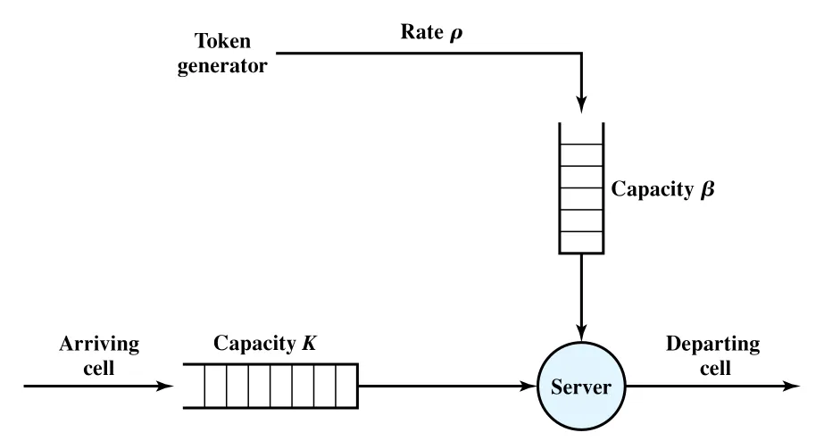 Figure 13.11 · PDF p. 424 · token bucket 기반 traffic shaping 구조
Figure 13.11에서 token generator는 초당 tokens를 만들고 최대 tokens를 담을 수 있는 token bucket에 넣는다. Source에서 오는 cell은 최대 cells를 담는 buffer에 저장된다. Server를 통해 cell 하나를 보내려면 token 하나를 꺼내야 한다. Bucket이 비어 있으면 cell은 다음 token이 생길 때까지 queue에서 기다린다.
Backlog가 있고 bucket이 비어 있는 상태에서는 cell이 cells/s의 smooth flow로 방출된다. 따라서 burst가 들어와도 output은 더 일정해지고, cell delay variation이 줄어든다.
13.7 ATM-GFR Traffic Management
**Guaranteed Frame Rate (GFR)**는 end system 관점에서는 **UBR (Unspecified Bit Rate)**처럼 단순하게 보이면서, ATM network element에는 비교적 낮은 processing complexity와 overhead로 minimum capacity guarantee를 제공하려는 service다. GFR에서 end system은 자기가 보내는 traffic을 policing하거나 shaping하지 않아도 되며, ATM adapter의 line rate로 전송할 수 있다.
UBR과 마찬가지로 GFR도 frame delivery를 절대 보장하지 않는다. Dropped frame이 생기면 TCP 같은 higher layer가 window management와 congestion control로 반응해야 한다. 그러나 UBR과 달리 GFR은 각 GFR VC에 대해 cell rate 기준의 일정 capacity를 reserve할 수 있다. 즉 application은 minimum rate에서는 loss 없이 전송할 수 있다는 보장을 받고, network가 congested하지 않으면 더 높은 rate로도 보낼 수 있다.
GFR의 독특한 점은 network가 cell뿐 아니라 frame도 인식해야 한다는 것이다. Congestion이 생기면 network는 individual cell이 아니라 entire frame을 discard한다. 또한 한 frame에 속한 모든 cell은 같은 CLP bit setting을 가져야 한다. AAL5 frame은 lower-priority frame으로 best-effort basis에서 전송되고, minimum guaranteed capacity는 frame에 적용된다.
GFR traffic contract는 다음 parameter로 구성된다.
| Parameter | 의미 |
|---|---|
| PCR (Peak Cell Rate) | VC가 낼 수 있는 peak cell rate |
| MCR (Minimum Cell Rate) | GFR이 보장하려는 최소 cell rate |
| MBS (Maximum Burst Size) | 허용되는 최대 burst 크기 |
| MFS (Maximum Frame Size) | 허용되는 최대 frame 크기 |
| CDVT (Cell Delay Variation Tolerance) | cell delay variation tolerance |
GFR Rate Guarantee를 지원하는 세 mechanism
GFR에서 per-VC guarantee를 제공하고 여러 user가 available capacity를 효율적이고 공정하게 공유하도록 만드는 기본 접근은 세 가지다.
| Mechanism | 역할 |
|---|---|
| Tagging and policing | GFR traffic contract를 지키는 frame과 그렇지 않은 frame을 구분하고, nonconforming frame의 cell을 tag/discard한다. |
| Buffer management | congestion 시 buffer 안팎의 tagged cell을 우선 discard하고, per-VC buffer/threshold로 fair sharing을 돕는다. |
| Scheduling | untagged cell 또는 eligible frame을 우선 처리하고, per-VC scheduling으로 MCR 보장을 지원한다. |
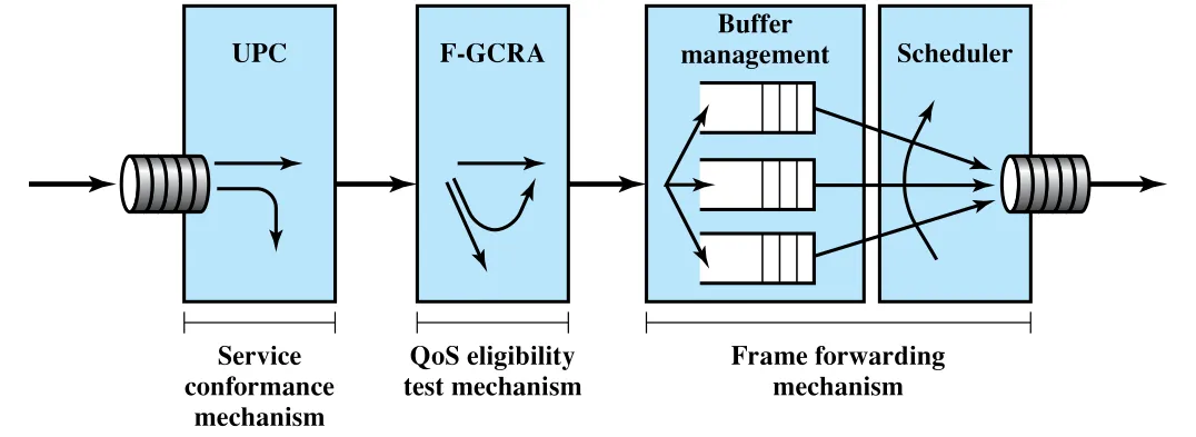 Figure 13.12 · PDF p. 426 · GFR mechanism의 conformance, QoS eligibility, forwarding 구성
Figure 13.12는 GFR을 세 단계로 보여준다. 먼저 UPC가 service conformance를 검사한다. 그다음 F-GCRA 같은 QoS eligibility test mechanism이 어떤 frame이 QoS guarantee 대상인지 판단한다. 마지막으로 buffer management와 scheduler가 frame forwarding mechanism을 구성한다.
Tagging and Policing
Tagging은 GFR traffic contract에 conform하는 frame과 그렇지 않은 frame을 구별한다. Conformance checking을 수행하는 network element는 nonconforming frame의 모든 cell에 을 설정한다. Tagged cell은 traffic contract violation으로 간주되며, 이후 buffer management나 scheduling에서 untagged cell보다 낮은 QoS를 받는다.
Tagging은 보통 ATM network ingress element에서 network가 수행할 수 있지만, source end system이 덜 중요한 frame을 표시하기 위해 직접 수행할 수도 있다. Network는 ingress 또는 다른 ATM switching element에서 인 nonconforming frame의 cell을 discard할 수 있고, 이 cell discard는 policing function에 해당한다.
Buffer Management
Buffer management는 switch에 이미 buffered된 cell 또는 forwarding 전 buffer에 들어와야 하는 cell을 어떻게 처리할지 결정한다. Congestion 상태, 즉 buffer occupancy가 높을 때 network element는 untagged cell보다 tagged cell을 먼저 discard한다. 경우에 따라 buffer에 이미 들어 있는 tagged cell을 버려 incoming untagged cell을 위한 공간을 만들 수 있다.
Fair하고 efficient한 buffer 사용을 위해 network element는 per-VC buffering을 사용할 수 있다. 각 VC에 일정 buffer space를 할당하고, 각 VC의 traffic contract와 per-VC buffer occupancy를 기준으로 cell discard decision을 내린다. 이 경우 discard는 전체 buffer occupancy 하나가 아니라 queue-specific occupancy threshold에 기반할 수 있다.
Scheduling
Scheduling은 최소한 untagged cell을 tagged cell보다 우선 처리할 수 있다. 더 나아가 VC별 separate queue를 유지하고 per-VC scheduling decision을 수행할 수 있다. 각 queue 내부에서는 first-come, first-served discipline을 쓰되 frame에 higher priority를 줄 수 있다.
Queue 사이 scheduling은 individual VC의 outgoing rate를 제어한다. 그 결과 각 VC가 fair allocation of capacity를 받고, GFR traffic contract의 MCR (Minimum Cell Rate) 요구를 만족하도록 만들 수 있다.
GFR Conformance와 QoS Eligibility
Figure 13.12의 첫 기능은 UPC다. UPC는 active VC별 traffic이 traffic contract를 지키는지 감시하고, nonconforming cell을 tag하거나 discard한다. GFR에서는 frame 단위 판정이 중요하다. Frame은 모든 cell이 conforming이면 conforming frame이고, 하나 이상의 cell이 nonconforming이면 nonconforming frame이다.
Cell이 conforming이 되려면 세 조건을 만족해야 한다.
| 조건 | 설명 |
|---|---|
| cell rate contract 준수 | cell rate가 contract 안에 있어야 한다. |
| frame 내 CLP consistency | 현재 cell의 CLP bit가 frame 첫 cell의 CLP bit와 같아야 한다. |
| MFS 준수 | cell이 frame의 last cell이거나, 현재 cell까지의 frame cell 수가 MFS보다 작아야 한다. |
QoS eligibility test는 사실상 two-stage filtering이다.
| Stage | 기준 | 결과 |
|---|---|---|
| Conformance test | traffic upper bound를 넘는지 검사 | nonconforming frame은 즉시 discard되거나 로 tag되어 이후 discard에 취약해진다. |
| QoS eligibility test | GFR contract의 lower bound, 즉 guarantee 대상 traffic인지 검사 | eligible frame은 QoS guarantee 대상이 되고, ineligible traffic은 best-effort에 가깝게 처리된다. |
따라서 GFR VC 위 frame은 세 범주로 나뉜다.
| Frame category | 처리 |
|---|---|
| Nonconforming frame | cell이 tagged 또는 discarded된다. |
| Conforming but ineligible frame | best-effort service를 받는다. |
| Conforming and eligible frame | delivery guarantee 대상이 된다. |
Eligibility 판단에는 Section 13.6의 cell rate algorithm 계열이 사용된다. Network는 eligible하지 않은 cell을 discard하거나 tag할 수 있다. 다만 Traffic Management Specification 4.1은 conforming but ineligible traffic도 available resource 기반으로 전달하려고 시도하는 것을 기대하며, 각 GFR connection이 각 link에서 local residual bandwidth의 fair share를 받도록 하는 방향을 제시한다.
핵심 용어 정리
| 용어 | 정리 |
|---|---|
| backpressure | congested node에서 upstream 방향으로 flow restriction을 전파하는 hop-by-hop congestion control |
| choke packet | congested node/router/host가 source에게 rate 감소를 요청하는 control packet |
| implicit congestion signaling | delay 증가나 loss 같은 징후로 end system이 congestion을 추론하는 방식 |
| explicit congestion signaling | network가 bit/control packet으로 congestion을 end system에게 직접 알리는 방식 |
| traffic management | fairness, QoS, reservation, policing, shaping을 포함해 congestion을 예방/완화하는 정책 집합 |
| quality of service (QoS) | delay, loss, variation, priority 등 application 요구에 맞춘 service quality |
| reservations / traffic contract | connection setup 시 network와 user가 traffic parameter와 QoS를 합의하는 구조 |
| cell delay variation (CDV) | ATM cell arrival/delivery timing의 변동성 |
| CIR / Bc / Be | frame relay에서 committed information rate, committed burst size, excess burst size |
| FECN / BECN / DE bit | frame relay에서 forward/backward congestion notification과 discard eligibility를 나타내는 bit |
| PCR / SCR / MCR / MBS / MFS / CDVT | ATM/GFR traffic contract를 정의하는 rate, burst, frame size, delay variation parameter |
| UPC / CAC / token bucket | ATM에서 admission, contract compliance monitoring, traffic shaping을 수행하는 주요 기능 |