개요
Chapter 24는 Internet 위에서 multimedia application을 지원할 때 필요한 핵심 기술을 다룬다. multimedia는 text, still image, audio, video 같은 여러 정보 형식을 함께 사용하는 것을 뜻한다. Broadband Internet access가 넓어지면서 Web-based/Internet-based multimedia application이 중요해졌고, 이 장은 그중에서도 compression, real-time traffic, SIP(Session Initiation Protocol), RTP(Real-Time Transport Protocol)를 중심으로 설명한다.
이 장의 흐름은 audio/video data를 줄이는 방법 → real-time traffic의 특성 → VoIP/multimedia session을 설정하는 SIP → 실제 real-time media를 운반하고 제어하는 RTP/RTCP다. 앞 장의 HTTP가 일반 Web resource exchange를 설명했다면, 이 장은 시간 제약과 media stream이 있는 application에서 어떤 추가 구조가 필요한지를 보여준다.
핵심 개념
| 주제 | 핵심 질문 | 검색용 용어 |
|---|---|---|
| Audio/video compression | Multimedia bit rate를 어떻게 줄이면서 품질을 유지하는가? | lossless compression, lossy compression, MPEG, MP3, PCM, PAM |
| MPEG audio | Human hearing의 한계를 어떻게 compression에 이용하는가? | simultaneous auditory masking, psychoacoustic analysis, bit allocation, entropy coding |
| MPEG video | Frame 사이 redundancy를 어떻게 제거하는가? | intraframe mode, interframe mode, DCT, quantization, motion compensation |
| Picture structure | I/P/B frame을 왜 섞고 transmission order를 바꾸는가? | I frame, P frame, B frame, macroblock, motion vector, bidirectional interpolation |
| Real-time traffic | Multimedia traffic은 ordinary data traffic과 무엇이 다른가? | hard real-time, soft real-time, jitter, delay variation, playback buffer |
| SIP | Multimedia session을 어떻게 설정/수정/종료하는가? | SIP, SDP, VoIP, user agent, proxy server, redirect server, registrar |
| RTP/RTCP | Real-time media stream을 어떻게 timestamping, sequencing, feedback하는가? | RTP, RTCP, RTP session, payload type, SSRC, jitter, sender report |
세부 정리
24.1 Audio and Video Compression
Multimedia application에서는 transmission capacity를 효율적으로 쓰는 것이 중요하다. Raw audio/video는 bit rate가 매우 크고, Internet path의 bandwidth는 항상 충분하지 않다. 따라서 이 절은 MPEG(Moving Picture Experts Group) 표준 계열을 중심으로 audio/video compression의 기본 원리를 설명한다.
MPEG는 ISO 산하에서 digital video와 associated audio를 저장/전송하기 위한 표준을 발전시켰다. 저장 매체는 CD-ROM, tape, writable optical disk가 될 수 있고, 전송 채널은 ISDN, LAN 등이 될 수 있다. 원문의 기본 전제는 video signal을 약 1.5 Mbps 수준으로 압축해도 acceptable quality를 얻을 수 있고, audio에도 그에 대응하는 효율을 얻을 수 있다는 것이다.
Lossless Compression과 Lossy Compression
Data compression은 크게 lossless compression과 lossy compression으로 나뉜다.
| 구분 | 의미 | 장점 | 한계 |
|---|---|---|---|
lossless compression | 정보 손실이 없고 decompressed data가 original uncompressed data와 동일하다. | 완전 복원이 가능하다. | 압축률은 data source의 entropy/redundancy 제거 범위로 제한된다. |
lossy compression | Decompressed data가 original의 acceptable approximation이면 된다. | 훨씬 높은 압축률을 얻을 수 있다. | Fidelity criterion에 따라 품질 손실이 생길 수 있다. |
Image/video에서는 “human eye가 original과 구분하지 못하는가”가 fidelity criterion이 될 수 있다. Audio에서도 MPEG 방식은 실제로는 lossy 원리를 사용하지만, 출력 fidelity가 매우 높아 실용적으로 lossless처럼 느껴질 수 있다. 이 장의 핵심은 “사람의 감각이 감지하지 못하는 정보는 버리거나 적은 bit로 표현해도 된다”는 설계 관점이다.
Audio Compression
Audio compression은 먼저 analog audio signal을 digitize하는 데서 출발한다. Chapter 5의 PCM(Pulse Code Modulation)은 sampling theorem을 이용한다. Sampling rate가 signal의 최고 frequency의 두 배보다 높으면 samples는 original signal 정보를 담고, lowpass filter로 재구성할 수 있다. 그러나 digital signal을 만들려면 각 sample을 fixed number of bits로 quantize해야 하므로, infinite precision인 PAM(Pulse Amplitude Modulation)과 달리 PCM은 original의 approximation이다.
단순히 sampling frequency나 bits per sample을 줄이면 더 압축할 수 있지만 fidelity가 직접 손상된다. MPEG audio는 더 나은 접근을 취한다. 핵심은 human hearing physiology, 특히 simultaneous auditory masking을 이용하는 것이다.
simultaneous auditory masking은 두 sound signal이 충분히 가까운 frequency/time 영역에 있고 한 tone이 강하면 약한 tone이 perceived되지 않는 현상이다. Human nervous system이 약한 signal을 mask하므로, 약한 tone을 제거하거나 더 거칠게 표현해도 listener가 차이를 못 느낄 수 있다.
Figure 24.1은 MPEG audio encoder/decoder의 큰 흐름을 보여준다.
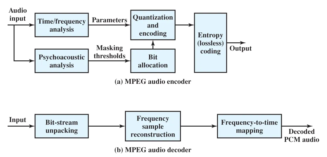 Figure 24.1 · PDF p. 821 · MPEG audio encoder가 time/frequency analysis, psychoacoustic analysis, bit allocation, entropy coding을 거쳐 압축하고 decoder가 역과정을 수행하는 구조
MPEG audio encoder는 다음 흐름으로 동작한다.
| 단계 | 역할 |
|---|---|
time/frequency analysis | Audio input을 2-50 ms time frame으로 나누고 각 frame을 frequency subband 또는 더 복잡한 parameter set으로 분해한다. |
psychoacoustic analysis | 같은 time frame에서 masking threshold와 compression에 이용 가능한 auditory property를 계산한다. |
bit allocation | 전체 available code bits를 subband signal quantization에 어떻게 배분할지 결정한다. Masking되는 영역에는 적은 bit를 쓸 수 있다. |
quantization and encoding | Subband parameter를 quantize하고 encode한다. |
entropy(lossless) coding | Digital signal의 redundancy를 제거해 추가 compression을 얻는다. |
Decoder는 bit-stream unpacking으로 lossless compression을 되돌리고, frequency sample reconstruction과 frequency-to-time mapping을 거쳐 decoded PCM audio를 만든다. 여기서 중요한 trade-off는 “감각적으로 들리지 않는 세부를 줄이면 bit rate를 크게 낮출 수 있지만, psychoacoustic model이 부정확하면 audible artifact가 생길 수 있다”는 점이다.
Video Compression
Moving picture는 still picture의 sequence다. 따라서 각 frame을 독립적인 still image로 압축하는 것만으로도 어느 정도 compression이 된다. 하지만 video sequence에서는 adjacent frames 사이 차이가 단일 frame의 전체 정보량보다 훨씬 작다. MPEG video compression은 이 temporal redundancy를 활용한다.
Figure 24.2는 MPEG video compression의 큰 block diagram이다. Intraframe mode와 interframe mode가 함께 쓰이며, DCT(Discrete Cosine Transform), Q(quantizer), VLC(variable-length coder), FM(frame memory), ME(motion estimator)가 핵심 구성요소다.
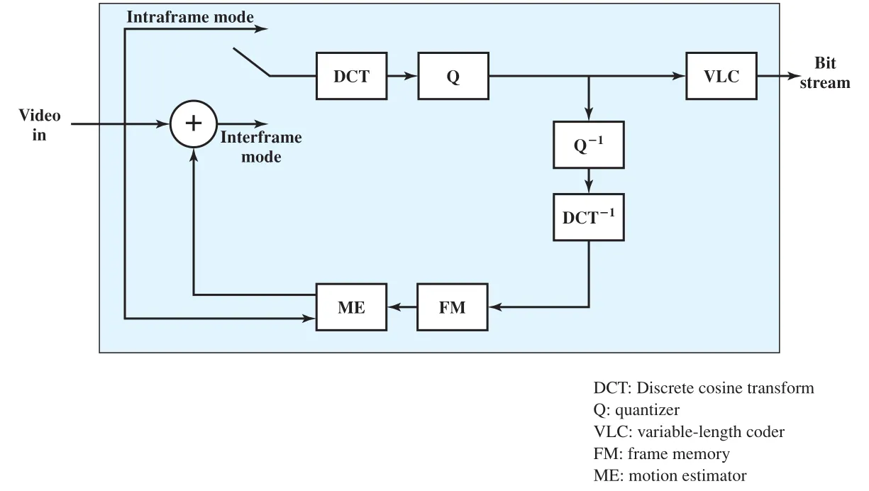 Figure 24.2 · PDF p. 822 · MPEG video compression에서 intraframe/interframe mode, DCT, quantization, variable-length coding, motion estimation이 연결되는 구조
intraframe mode에서는 각 frame을 하나의 still image로 처리한다. 기본 단계는 다음과 같다.
| 단계 | 의미 | 압축 관점 |
|---|---|---|
| Preliminary scaling/color conversion | Frame을 SIF(Source Input Format)로 변환하고 color representation을 YUV로 바꾼다. | 표준화된 입력 표현을 만든다. |
| Color subsampling | Human eye는 brightness에 더 민감하고 hue에는 덜 민감하므로 hue information을 크게 줄인다. | Subjective fidelity를 크게 해치지 않고 color data를 줄인다. |
DCT(Discrete Cosine Transform) | 8 x 8 pixel block을 frequency-domain-like coefficient set으로 mapping한다. | 직접 압축은 아니지만 뒤 단계가 압축하기 좋은 표현을 만든다. |
| Quantization | DCT values를 finite set으로 quantize한다. | Level 수가 많으면 fidelity가 높고 compression은 낮다. |
| Run-length encoding | Quantized DCT values의 반복/0-run을 압축 표현한다. | Quantization 후 생긴 반복성을 활용한다. |
| Huffman coding | 자주 나오는 bit sequence에 짧은 symbol을 배정한다. | Lossless coding으로 bit stream redundancy를 줄인다. |
Still-image 방식만 쓰면 frame 간 redundancy를 놓친다. 대부분 pixel은 다음 frame에서도 거의 같거나, pattern이 근처 위치로 이동했을 뿐이다. MPEG는 interframe mode에서 이 redundancy를 추가로 제거한다. 원문은 이런 interframe 처리가 추가로 약 3배 정도의 compression을 줄 수 있다고 설명한다.
Motion Compensation
MPEG interframe compression의 기반은 motion compensation이다. 어떤 frame의 image portion은 가까운 frame의 equal-sized portion과 같거나 매우 비슷하다는 점을 이용한다. MPEG는 motion compensation에 prediction과 interpolation을 사용한다.
Figure 24.3은 block motion compensation의 핵심을 보여준다. Current frame의 16 x 16 macroblock을 previous/future decompressed frame의 유사 block과 비교하고, 위치 차이를 motion vector로 표현한다.
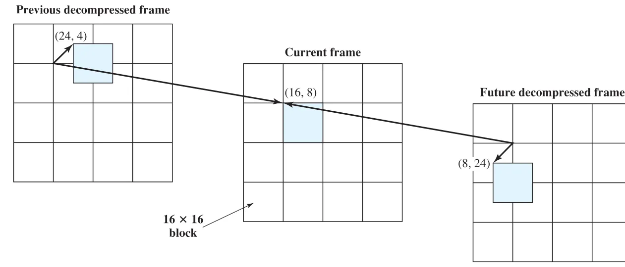 Figure 24.3 · PDF p. 824 · current frame의 macroblock을 previous/future decompressed frame의 matching block으로 예측하는 block motion compensation
prediction에서는 current frame의 각 16 x 16 macroblock을 preceding anchor frame의 matching block으로 표현한다. Matching block의 displacement가 motion vector다. 원문 예시에서는 current frame의 macroblock 위치가 (16, 8)이고 previous frame의 matching block 위치가 (24, 4)라서 motion vector가 (8, -4)가 된다.
Predictive coding에서 주의할 점은 두 가지다.
- Matching macroblock은 반드시 16-pixel boundary 위에 있을 필요가 없다.
- Matching은 previous source frame이 아니라 compression/decompression을 거친 frame을 기준으로 한다. Decoder는 source frame을 갖고 있지 않고 decompressed version만 갖기 때문이다.
Prediction error는 current macroblock과 reference macroblock의 pixel difference matrix다. 개념적으로는 다음과 같다.
이 error matrix에는 0 또는 작은 값이 많으므로 original pixel matrix보다 DCT-quantization 후 더 잘 압축된다. MPEG 표준은 matching process 자체를 강제하지 않는다. 보통 search range 안의 candidate displacement 중 cost function을 최소화하는 displacement를 motion vector로 선택한다.
Bidirectional Interpolation과 I/P/B Frame
bidirectional interpolation은 current frame을 past reference frame 하나만이 아니라 past/future reference frame 둘로 예측한다. 예를 들어 scene이 frame마다 half-pixel씩 이동한다면, 직전 frame이나 직후 frame만으로는 exact match가 없지만 두 frame의 best match를 평균하면 정확한 예측이 가능할 수 있다. 이 경우 error matrix가 모두 0에 가까워져 compression이 좋아진다.
MPEG는 세 종류의 picture frame을 정의한다.
| Frame type | 의미 | Reference 관계 |
|---|---|---|
I frame(Intraframe) | JPEG-style independent still image로 encoded된다. | 다른 frame 없이 decode 가능하다. |
P frame(Predicted) | 가장 가까운 preceding I/P anchor frame을 기준으로 encoded된다. | 과거 anchor frame 참조 |
B frame(Bidirectional interpolated) | 가장 가까운 preceding/following I/P anchor frame을 기준으로 encoded된다. | 과거와 미래 anchor frame 참조 |
B frame의 macroblock은 세 mode 중 하나를 선택한다.
| B picture mode | Predictor |
|---|---|
forward predicted | preceding reference frame의 block |
backward predicted | following reference frame의 block |
average | preceding/following reference block의 average |
Frame type 비율은 configurable하지만 trade-off가 있다. I frame이 많으면 random access와 fast forward/reverse search가 쉬워지지만 compression efficiency는 낮아진다. B frame이 많으면 compression ratio는 좋아질 수 있지만 computation이 늘고, B frame은 다른 B frame의 reference가 될 수 없으므로 reference와의 average distance가 커져 correlation이 약해질 수 있다.
Figure 24.4는 temporal picture structure와 transmission order 재배치를 보여준다.
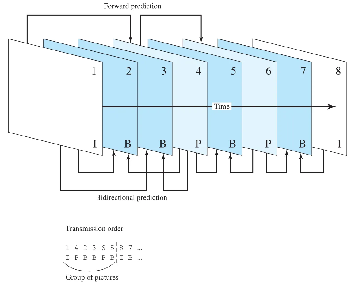 Figure 24.4 · PDF p. 827 · MPEG에서 I/P/B frame의 display time과 transmission order가 달라지는 temporal picture structure
Display order와 transmission order가 달라지는 이유는 B frame이 both preceding and following reference frame을 필요로 하기 때문이다. 예를 들어 display order가 I B B P ...라면, B frames를 decode하려면 뒤의 P frame이 먼저 도착해야 한다. 그래서 transmission order는 reference frame을 먼저 보내도록 재배치된다.
display order:      I  B  B  P  B  P  B  I ...
transmission order: I  P  B  B  P  B  I  B ...
이 구조는 MPEG compression이 단순히 “frame을 작게 저장”하는 문제가 아니라, decoding dependency, random access, search 기능, computation, compression ratio 사이의 균형 문제임을 보여준다.
24.2 Real-Time Traffic
High-speed LAN/WAN과 Internet line capacity가 커지면서 IP-based network로 real-time traffic을 운반할 가능성이 커졌다. 하지만 real-time traffic의 요구사항은 high-speed non-real-time traffic과 다르다.
Traditional Internet applications, 예를 들어 file transfer, electronic mail, Web client/server application에서는 관심 지표가 보통 throughput, delay, reliability다. Data가 lost/corrupted/misordered되지 않는 것이 중요하다. 반면 real-time application은 timing issue가 더 중요하다. 많은 경우 data가 sending rate와 같은 constant rate로 delivered되어야 하고, 어떤 경우에는 data block마다 deadline이 있어서 deadline이 지나면 data가 더 이상 usable하지 않다.
Real-Time Traffic Characteristics
Figure 24.5는 real-time audio stream의 전형적인 구조를 보여준다. Source multimedia server가 64 kbps audio를 만들고, 160 data octets를 담은 packet을 20 ms마다 전송한다. Internet을 지나 destination multimedia PC에 도착하면 packet interarrival time이 더 이상 정확히 20 ms가 아니다. Internet이 variable delay를 만들기 때문이다.
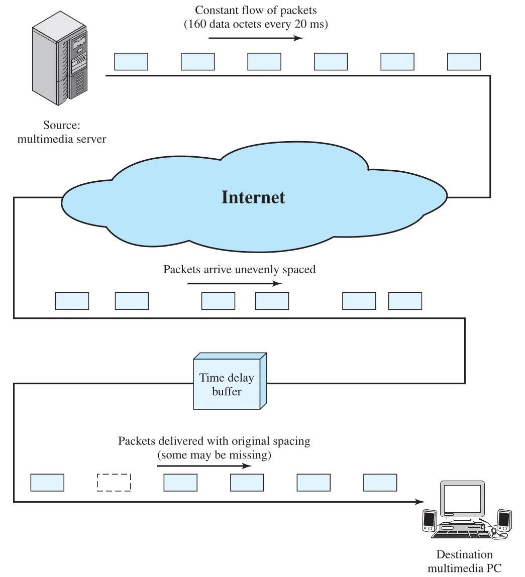 Figure 24.5 · PDF p. 828 · 일정 간격으로 생성된 real-time packets가 Internet delay variation 때문에 불균등하게 도착하고 delay buffer로 재정렬되는 구조
Destination은 incoming packets를 time delay buffer에 넣고 약간 지연시킨 뒤 일정 rate로 audio generation software에 넘긴다. 이 buffer가 있으면 network jitter를 어느 정도 흡수할 수 있지만, buffer compensation은 무한하지 않다.
delay jitter는 하나의 session에서 packet들이 경험하는 delay의 maximum variation이다. 예를 들어 어떤 packet의 minimum end-to-end delay가 1 ms이고 maximum delay가 6 ms라면 delay jitter는 5 ms다. Time delay buffer가 incoming packet을 최소 5 ms 지연시키면 모든 incoming packet을 순서에 맞춰 내보낼 수 있다. 하지만 buffer delay가 4 ms라면 relative delay가 4 ms를 넘은 packet은 late packet이 되며, playback order를 깨지 않기 위해 discard될 수 있다.
Real-time traffic이 항상 fixed-size packet을 fixed interval로 만드는 것은 아니다. Figure 24.6은 세 가지 traffic profile을 비교한다.
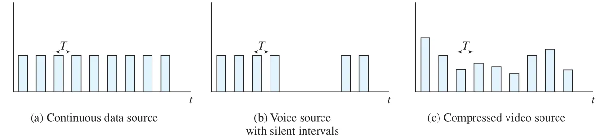 Figure 24.6 · PDF p. 829 · continuous data source, on/off voice source, compressed video source의 real-time packet 생성 패턴 비교
| Traffic profile | Packet pattern | 예시 | 설계상 의미 |
|---|---|---|---|
continuous data source | Fixed-size packets at fixed intervals | air traffic control radar, real-time simulations | Constant rate 유지가 중요하고 lossy compression이 부적절할 수 있다. |
on/off source | Activity period에는 fixed-size packets at fixed intervals, inactivity period에는 silence | telephony, audio conferencing | Voice silence interval 때문에 traffic burst/idle pattern이 생긴다. |
variable packet size | Uniform interval이지만 packet length가 변한다. | compressed digitized video | 같은 output quality에서도 frame별 compression ratio가 달라 packet size가 변한다. |
Requirements for Real-Time Communication
Real-time communication에 바람직한 특성은 다음과 같다.
| Requirement | 의미 |
|---|---|
low jitter | Playback buffer가 감당해야 할 delay variation을 줄인다. |
low latency | Interactive voice/video에서 대화 지연을 줄인다. |
| integration of real-time and non-real-time services | 같은 network에서 ordinary data와 real-time stream을 함께 다룰 수 있어야 한다. |
| adaptability | Network/traffic condition이 바뀌면 rate, encoding, buffering 등을 조정할 수 있어야 한다. |
| scalability | Large networks와 large number of connections에서도 성능을 유지해야 한다. |
| modest buffer requirements | Network 내부와 end system의 buffer 부담이 지나치게 커지면 안 된다. |
| high effective capacity utilization | Real-time 요구를 만족하면서도 capacity를 낭비하지 않아야 한다. |
| low header overhead | 작은 real-time packet에서 header bits per packet이 커지면 효율이 나빠진다. |
| low processing overhead | Network node와 end system에서 packet당 처리 비용이 작아야 한다. |
Wide area IP-based network에서 이 요구사항을 모두 만족하기는 어렵다. 원문은 TCP나 UDP만으로는 충분하지 않다고 설명한다. TCP는 reliable ordered byte stream을 제공하지만 retransmission과 congestion behavior가 real-time deadline과 맞지 않을 수 있다. UDP는 가볍지만 sequencing, timing, payload identification, feedback 같은 real-time support를 직접 제공하지 않는다. 이 빈틈을 채우는 기반으로 뒤에서 RTP(Real-Time Transport Protocol)가 등장한다.
Hard Real-Time과 Soft Real-Time
Real-time application은 hard real-time과 soft real-time으로 구분된다.
| 구분 | 의미 | 우선순위 |
|---|---|---|
soft real-time applications | 일부 communicated data loss를 tolerate할 수 있다. | Network utilization을 높이는 것이 어느 정도 packet loss/misordering보다 중요할 수 있다. |
hard real-time applications | Zero loss tolerance를 가진다. | Deterministic upper bound on jitter와 high reliability가 network utilization보다 우선한다. |
VoIP나 audio/video conferencing은 보통 일부 packet loss를 concealment로 견딜 수 있는 soft real-time 성격을 가진다. 반면 제어/안전 관련 real-time application은 missed deadline이나 loss가 시스템 실패로 이어질 수 있어 hard real-time 요구가 강하다.
24.3 Voice Over IP and Multimedia Support: SIP
SIP(Session Initiation Protocol)는 IP data network 위에서 participants 사이의 real-time session을 설정, 수정, 종료하기 위한 application-level control protocol이다. SIP의 중요한 동기는 Internet telephony, 즉 VoIP(voice over IP)를 가능하게 하는 것이다. 하지만 SIP는 voice에만 한정되지 않고 teleconferencing 같은 single media 또는 multimedia session을 지원할 수 있다.
SIP가 다루는 것은 media 자체의 실시간 전송이 아니라 session control이다. 실제 media stream은 보통 뒤에서 다루는 RTP로 전송되고, SIP는 누가 참여하는지, 어떤 media를 쓸지, 어디로 연락할지, session을 어떻게 변경/종료할지를 조정한다.
SIP는 multimedia communication의 establishment/termination에서 다섯 가지 facet을 지원한다.
| SIP facet | 의미 |
|---|---|
User location | 사용자가 이동하더라도 remote location에서 telephony/application features에 접근할 수 있게 한다. |
User availability | Called party가 communication에 참여할 의사가 있는지 결정한다. |
User capabilities | 사용할 media와 media parameters를 결정한다. |
Session setup | Point-to-point 또는 multiparty call을 agreed session parameters와 함께 설정한다. |
Session management | Session transfer/termination, session parameter modification, service invocation을 포함한다. |
SIP는 이전 장에서 본 기술 요소를 적극적으로 재사용한다.
| 연결되는 기술 | SIP에서의 사용 |
|---|---|
HTTP | HTTP-like request/response transaction model, readable text-based format, many header fields/encoding rules/status codes를 사용한다. |
DNS | Recursive/iterative search와 유사한 방식으로 target user/domain을 찾고, domain name 기반으로 proxy server를 찾는다. |
MIME/SDP | SIP message body에 SDP(Session Description Protocol) encoded session description을 넣어 media content를 설명한다. |
SIP Components and Protocols
SIP network는 client/server 관점과 individual network element 관점에서 볼 수 있다.
| SIP role | 의미 |
|---|---|
Client | SIP requests를 보내고 SIP responses를 받는 network element. User agent client와 proxy가 client가 될 수 있다. |
Server | Requests를 받아 service하고 responses를 돌려주는 network element. Proxy, user agent server, redirect server, registrar 등이 server가 될 수 있다. |
개별 SIP network element는 다음과 같다.
| SIP element | 역할 |
|---|---|
User Agent(UA) | SIP end station에 있으며 두 역할을 가진다. UAC(User Agent Client)는 SIP request를 발행하고, UAS(User Agent Server)는 SIP request를 받아 accept/reject/redirect response를 만든다. |
Redirect Server | Session initiation 중 called device address를 결정하고, UAC가 alternate URI에 contact하도록 정보를 돌려준다. DNS의 iterative search와 유사하다. |
Proxy Server | 다른 client를 대신해 request를 만드는 intermediary다. Request를 targeted user에 가까운 entity로 routing하고, policy enforcement도 할 수 있다. 필요하면 request 일부를 interpret/rewrite한 뒤 forwarding한다. DNS의 recursive search와 유사하다. |
Registrar | User agent의 REGISTER request를 받아 SIP address와 associated IP address를 domain의 location service에 넣는다. |
Location Service | Redirect/proxy server가 callee의 possible location을 얻기 위해 사용하는 service다. SIP-address/IP-address mapping database를 유지한다. |
Figure 24.7은 SIP control path와 media path를 함께 보여준다. Alice와 Bob의 user agent 사이에서 SIP/SDP는 session setup/control에 쓰이고, session이 설정된 뒤 media는 RTP로 흐른다.
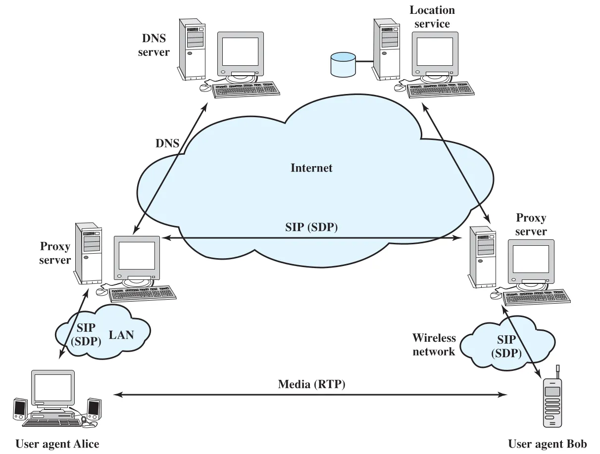 Figure 24.7 · PDF p. 832 · SIP user agents, proxy server, DNS, location service, SDP, RTP media path의 관계
Proxy server는 필요하면 redirect server처럼 동작할 수 있고, redirection이 필요하면 location service database를 consult한다. Proxy server와 location service 사이의 통신 방식은 SIP standard 범위 밖이다. 또한 SIP operation에는 DNS가 중요하다. UAC는 보통 UAS의 IP address가 아니라 domain name을 사용해 request를 만들고, proxy server는 target domain의 proxy server를 찾기 위해 DNS server를 consult한다.
Transport 측면에서 SIP는 performance 이유로 보통 UDP 위에서 동작하고 자체 reliability mechanisms를 제공한다. 필요하면 TCP도 사용할 수 있다. Secure encrypted transport가 필요하면 Chapter 21에서 다룬 TLS(Transport Layer Security) 위에 SIP messages를 실을 수 있다.
SDP와 SIP URI
SIP와 함께 쓰이는 SDP(Session Description Protocol)는 SIP message body 안에서 session content를 설명한다. SIP가 one or more participants를 session에 invite하는 control protocol이라면, SDP는 voice/video 같은 media encodings, participant IP addresses, available transmission capacity, media type 등을 설명한다. 이 정보가 교환되고 acknowledged되면 실제 data transmission이 시작되며, 보통 RTP가 사용된다. Session 중에도 participants는 SIP messages로 media type 추가나 new party 추가 같은 session parameter change를 수행할 수 있다.
SIP network 안의 resource는 URI(Uniform Resource Identifier)로 식별된다. Resource 예시는 online service user, multiline phone appearance, messaging system mailbox, gateway service의 telephone number, organization group(sales, helpdesk) 등이다.
SIP URI는 email address와 비슷한 user@domain 형식에 기반한다.
sip:bob@biloxi.com
sips:bob@biloxi.com
sip: scheme은 일반 SIP URI이고, secure transmission이 필요하면 sips:를 사용한다. sips:의 경우 SIP messages는 TLS 위에서 전송된다. URI에는 password, port number, related parameters도 포함될 수 있다.
SIP Operation Examples
SIP specification은 매우 크지만, 원문은 Alice가 Bob에게 session을 시도하는 예로 동작 감각을 설명한다. 핵심은 SIP가 DNS, proxy server, location service, user agent response를 조합해 callee의 현재 위치와 availability를 확인한다는 점이다.
Figure 24.8은 Bob이 signed in 상태가 아니어서 session setup이 실패하는 흐름이다.
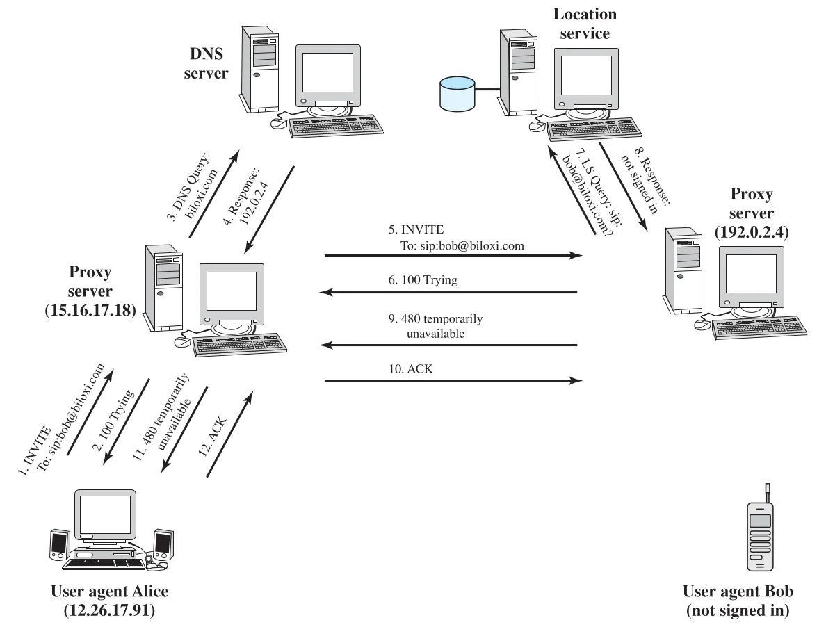 Figure 24.8 · PDF p. 834 · Alice가 Bob에게 INVITE를 보내지만 location service가 Bob unavailable을 반환하는 SIP call setup attempt
실패한 call setup 흐름은 다음과 같다.
- Alice의
UAC가 outbound proxy server에INVITE를 보낸다. - Outbound proxy는
100 Trying으로 request 수신을 알린다. - Bob의 URI는
sip:bob@biloxi.com이므로 outbound proxy는 DNS에biloxi.comproxy server의 SRV record를 질의한다. - DNS가 inbound proxy server IP address를 돌려준다.
- Outbound proxy가 inbound proxy로
INVITE를 forwarding한다. - Inbound proxy는 location service에 Bob의 location/availability를 묻는다.
- Location service가 Bob이 signed in 상태가 아니라고 알려준다.
480 Temporarily Unavailableresponse가 proxy들을 거쳐 Alice에게 돌아오고, Alice는ACK로 final response 수신을 확인한다.
원문은 이어서 SUBSCRIBE/NOTIFY 기반 presence example과 Bob의 REGISTER에 따른 registration/notification example을 보여준다. 여기서 중요한 것은 SIP가 단순히 “전화 걸기” request만 보내는 것이 아니라, callee availability 변화에 대한 subscription, registration, notification도 session control plane의 일부로 다룬다는 점이다. Bob이 나중에 signed in하면 location service가 update되고, Alice는 notification을 받은 뒤 다시 call setup을 시도할 수 있다.
Figure 24.11은 Bob이 registered된 뒤 successful call setup이 이뤄지는 흐름이다.
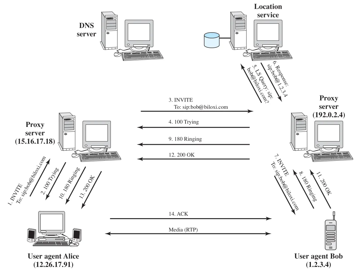 Figure 24.11 · PDF p. 837 · INVITE, 100 Trying, 180 Ringing, 200 OK, ACK 이후 RTP media session이 시작되는 SIP successful call setup
Successful flow에서 눈여겨볼 점은 다음과 같다.
| 단계 | 의미 |
|---|---|
INVITE | Alice가 Bob을 media session에 초대한다. 처음에는 proxy chain을 거쳐 target domain/user를 찾는다. |
100 Trying | Proxy/server가 request를 받았고 처리 중임을 알려주는 provisional response다. |
180 Ringing | Bob 쪽 UAS가 local media application, 예를 들어 telephony application을 alerting 중임을 알린다. |
200 OK | Bob이 call을 accept했고 final successful response가 Alice에게 돌아온다. |
ACK | Alice가 final response 수신을 확인한다. 이 예에서는 INVITE/200 OK exchange로 endpoints가 서로의 address를 알게 되어 ACK가 proxies를 우회해 Alice에서 Bob으로 직접 간다. |
Media(RTP) | SIP control exchange가 끝난 뒤 Alice와 Bob은 RTP connection으로 media data를 교환한다. |
SIP Messages
SIP는 HTTP와 유사한 text-based protocol이다. SIP message에는 request와 response 두 종류가 있으며, 두 종류의 차이는 first line에 나타난다.
| Message type | First line | Body 가능 여부 |
|---|---|---|
SIP request | method, Request-URI, SIP version | SDP media description 같은 body 가능 |
SIP response | SIP version, response code, reason phrase | SDP body 가능 |
모든 SIP message는 header를 포함한다. Header는 여러 줄로 구성되고, 각 줄은 header label로 시작한다. Message body에는 SDP media description이 들어갈 수 있다.
RFC 3261의 주요 SIP request methods는 다음과 같다.
| SIP method | 의미 |
|---|---|
REGISTER | User agent가 현재 IP address와 calls를 받고 싶은 URLs를 SIP network에 알린다. |
INVITE | User agents 사이에 media session을 설정한다. |
ACK | Reliable message exchange를 confirm한다. |
CANCEL | Pending request를 종료한다. 이미 완료된 call을 undo하지는 않는다. |
BYE | Conference 안의 두 users 사이 session을 종료한다. |
OPTIONS | Callee의 capabilities 정보를 요청하지만 call을 설정하지 않는다. |
Figure 24.11의 첫 INVITE request header는 다음 구조를 가진다.
INVITE sip:bob@biloxi.com SIP/2.0
Via: SIP/2.0/UDP 12.26.17.91:5060
Max-Forwards: 70
To: Bob <sip:bob@biloxi.com>
From: Alice <sip:alice@atlanta.com>;tag=1928301774
Call-ID: a84b4c76e66710@12.26.17.91
CSeq: 314159 INVITE
Contact: <sip:alice@atlanta.com>
Content-Type: application/sdp
Content-Length: 142
주요 header field의 의미는 다음과 같다.
| Header | 의미 |
|---|---|
Via | Request가 SIP network에서 지나온 path를 나타내며, response가 같은 path를 거슬러 돌아가는 데 쓰인다. Proxy가 forwarding할 때 추가 Via header를 붙인다. |
Max-Forwards | Request가 destination까지 갈 수 있는 hop 수를 제한한다. Proxy마다 1씩 감소하며 0이 되면 483 Too Many Hops로 reject된다. |
To | Request가 원래 향한 display name과 SIP/SIPS URI를 담는다. |
From | Request originator의 display name과 SIP/SIPS URI를 담고, session 식별에 쓰이는 tag parameter를 포함할 수 있다. |
Call-ID | Random string과 host name/IP address 조합으로 만든 globally unique call identifier다. |
CSeq(Command Sequence) | Integer와 method name을 포함한다. Dialog 안에서 new request와 retransmission을 구분하는 sequence number 역할을 한다. |
Contact | UAs 사이 future requests를 직접 보낼 SIP URI를 제공한다. Via가 response routing용이라면, Contact는 dialog 안의 future request target을 알려준다. |
Content-Type | Message body type을 나타낸다. 예시는 application/sdp다. |
Content-Length | Message body 길이를 octets 단위로 나타낸다. |
To tag, From tag, Call-ID의 조합은 Alice와 Bob 사이의 peer-to-peer SIP relationship을 완전히 정의하며, 이를 dialog라고 부른다.
SIP response category는 HTTP와 유사하다.
| Response class | 의미 |
|---|---|
1xx Provisional | Request가 received되어 processing 중이다. |
2xx Success | Action이 successfully received, understood, accepted되었다. |
3xx Redirection | Request를 완료하려면 further action이 필요하다. |
4xx Client Error | Request syntax가 나쁘거나 이 server에서 fulfill할 수 없다. |
5xx Server Error | Server가 apparently valid request를 fulfill하지 못했다. |
6xx Global Failure | 어떤 server에서도 request를 fulfill할 수 없다. |
Figure 24.11의 200 OK response는 SIP/2.0 200 OK로 시작하고, Via, To, From, Call-ID, CSeq, Contact, Content-Type, Content-Length 같은 headers를 포함한다. INVITE request에서 쌓인 multiple Via field values가 response에 복사되기 때문에 response는 proxy chain을 따라 되돌아갈 수 있다. Bob의 SIP phone은 To header에 tag parameter를 추가하고, 이 tag는 이후 call의 모든 requests/responses에 포함된다.
SDP 정보
SDP(Session Description Protocol)는 telephony, Internet radio, multimedia application 같은 session content를 설명한다. SDP가 포함할 수 있는 정보는 다음과 같다.
| SDP information | 의미 |
|---|---|
Media streams | Session 안의 audio, video, data, control, application 등 stream type |
Addresses | Media stream의 destination address. Multicast address일 수도 있다. |
Ports | 각 stream의 UDP send/receive port numbers |
Payload types | Telephony 같은 media stream에서 사용할 수 있는 media formats |
Start and stop times | Broadcast session의 start, stop, repeat time |
Originator | Broadcast session의 originator와 contact information |
SIP와 SDP의 관계는 “SIP는 초대/제어 메시지, SDP는 그 메시지 안에 실리는 media description”으로 기억하면 된다.
24.4 Real-Time Transport Protocol(RTP)
TCP는 distributed application에서 널리 쓰이지만, real-time distributed application에는 잘 맞지 않는다. 여기서 real-time distributed application은 source가 constant rate로 data stream을 만들고, one or more destinations가 같은 constant rate로 application에 전달해야 하는 application을 뜻한다. Audio/video conferencing, live video distribution, shared workspace, remote medical diagnosis, telephony, command/control systems, distributed interactive simulations, games, real-time monitoring 등이 예다.
TCP가 real-time media transport에 부적합한 이유는 다음과 같다.
| TCP 특성 | Real-time에서의 문제 |
|---|---|
| point-to-point connection | Multicast distribution에 적합하지 않다. |
| retransmission of lost segments | 늦게 도착한 retransmitted segment는 대부분 real-time playback에서 usable하지 않다. |
| timing information 부재 | Segment에 media timing을 연결하는 convenient mechanism이 없다. |
UDP는 multicast/connection 측면에서는 TCP보다 가볍고 retransmission도 강제하지 않지만, UDP만으로는 timing information과 real-time application에 필요한 general-purpose tools를 제공하지 않는다. 그래서 common real-time features를 담은 RTP(Real-Time Transport Protocol)가 정의된다. RTP는 soft real-time communication에 가장 적합하며, hard real-time traffic을 보장하는 mechanism은 부족하다.
RTP는 두 프로토콜로 구성된다.
| 구성 | 역할 |
|---|---|
RTP data transfer protocol | Real-time user data를 전송한다. 이 절에서 단순히 RTP라고 부르는 부분이다. |
RTCP(RTP Control Protocol) | RTP data delivery에 대한 control/feedback 정보를 제공한다. |
RTP Protocol Architecture
RTP의 중요한 철학은 RTP functionality와 application-layer functionality가 밀접하게 결합된다는 점이다. RTP는 application이 직접 사용해 하나의 protocol처럼 구현할 수 있는 framework에 가깝다. Application-specific information이 없으면 RTP는 완전한 protocol이 아니지만, RTP는 common structure와 function을 제공해 개별 real-time application이 모든 것을 새로 만들 필요를 줄인다.
RTP가 따르는 설계 원칙은 application-level framing과 integrated layer processing이다.
| 원칙 | 의미 |
|---|---|
application-level framing | Error recovery의 단위를 application이 지정한 ADU(Application-level Data Unit)로 본다. Lower layers는 ADU boundaries를 보존하고, 손실 복구 여부/방식은 application 의미에 맞춰 결정한다. |
integrated layer processing | 엄격한 layer 순서가 efficiency를 제한할 수 있으므로, 인접 계층 기능을 tightly coupled하게 구현할 수 있도록 본다. |
Application-level framing이 중요한 이유는 real-time audio/video가 “무조건 retransmission”보다 “품질을 낮추거나 늦은 data를 버리는” 쪽이 더 나을 수 있기 때문이다. 예를 들어 일부 data loss가 있더라도 재생을 계속할 수 있으면, source는 lost value retransmission 대신 lower-quality transmission으로 바꾸는 것이 더 합리적일 수 있다. 또한 application은 lost data를 recompute하거나, original lost value 대신 결과를 보정하는 new data를 보낼 수도 있다.
Figure 24.12는 RTP가 UDP 위에서 동작하면서도 application-specific media encoding과 결합되는 구조를 보여준다.
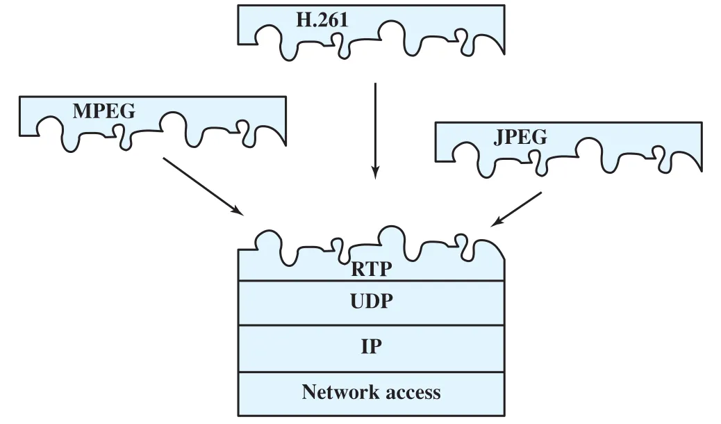 Figure 24.12 · PDF p. 842 · H.261, MPEG, JPEG 같은 media encoding이 RTP/UDP/IP 위에서 결합되는 RTP protocol architecture
UDP는 transport layer의 basic port addressing을 제공하고, RTP는 sequencing 같은 추가 transport-level function을 제공한다. 그러나 RTP는 payload-specific header extension이나 application-layer functionality와 결합되어야 완성된다. 이 때문에 RTP는 TCP처럼 opaque byte stream을 제공하는 protocol이 아니라, media application이 timing/format/sequence를 직접 이해하고 다루게 하는 framework로 보는 편이 정확하다.
RTP Concepts
RTP는 session 안의 여러 participants 사이에서 real-time data transfer를 지원한다. RTP session은 data transfer 기간 동안 유지되는 two or more RTP entities의 logical association이다.
RTP session은 다음 요소로 정의된다.
| Session 요소 | 의미 |
|---|---|
RTP port number | 모든 participants가 RTP transfer에 사용하는 destination port. UDP가 lower layer이면 UDP header의 Destination Port field에 들어간다. |
RTCP port number | 모든 participants가 RTCP transfer에 사용하는 destination port |
Participant IP addresses | Multicast IP address 또는 unicast IP address set. Multicast address이면 multicast group이 participants를 정의한다. |
Session setup 자체는 RTP/RTCP의 범위 밖이다. 앞 절의 SIP/SDP가 session establishment와 media parameter negotiation에 관여하고, RTP는 그 이후 media stream transport를 담당한다고 이해하면 된다.
RTP의 강점은 multicast real-time transmission 지원에 있다. 각 RTP data unit은 group 안에서 누가 data를 만들었는지 식별하는 source identifier를 포함한다. 또한 timestamp를 포함해 receiver가 delay buffer로 proper timing을 재구성할 수 있게 하고, payload format을 식별한다.
RTP는 두 종류의 relay를 허용한다: mixer와 translator.
| RTP relay | 의미 | 예시 |
|---|---|---|
mixer | 하나 이상의 source에서 온 RTP packet streams를 받아 결합하고, 새 RTP packet stream으로 forwarding한다. Timing을 새로 제공하고 자신을 synchronization source로 식별한다. | 여러 audio streams를 하나로 합쳐 low-capacity link를 가진 participant에게 전송 |
translator | Incoming RTP packet마다 하나 이상의 outgoing RTP packets를 만든다. Format 변경 또는 lower-level protocol suite 변경을 할 수 있다. | high-speed video를 lower-quality format으로 변환, firewall 양쪽에서 secure tunnel로 multicast relay, multicast packet을 여러 unicast destinations로 복제 |
Mixer는 여러 input stream의 timing이 보통 synchronized되어 있지 않으므로 combined packet stream에 대한 timing information을 제공한다. Translator는 더 단순하며 packet format/data rate/protocol domain을 바꾸는 데 초점이 있다.
RTP Fixed Header
모든 RTP packet은 fixed header를 포함하며, 추가 application-specific header fields를 포함할 수 있다. Figure 24.13은 RTP fixed header format을 보여준다.
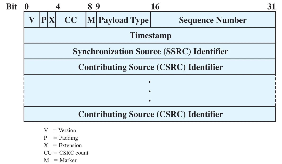 Figure 24.13 · PDF p. 844 · RTP fixed header의 V/P/X/CC/M/Payload Type/Sequence Number/Timestamp/SSRC/CSRC 필드 구조
처음 12 octets는 항상 존재한다.
| RTP header field | 크기 | 의미 |
|---|---|---|
Version(V) | 2 bits | Current RTP version. 원문 범위에서는 version 2 |
Padding(P) | 1 bit | Payload 끝에 padding octets가 있는지 표시한다. 마지막 octet은 padding octet count를 담는다. |
Extension(X) | 1 bit | Fixed header 뒤에 experimental RTP extension header가 정확히 하나 따라오는지 표시한다. |
CSRC Count(CC) | 4 bits | Fixed header 뒤에 따라오는 CSRC(Contributing Source) identifiers 수 |
Marker(M) | 1 bit | Payload type에 따라 해석된다. Video에서는 frame end, audio에서는 talk spurt beginning 같은 boundary 표시로 쓰인다. |
Payload Type | 7 bits | RTP payload format을 식별한다. Compression/encryption을 포함한 media type/format을 나타낸다. |
Sequence Number | 16 bits | Source가 random number로 시작해 RTP data packet마다 1씩 증가시킨다. Packet loss detection과 같은 timestamp 안의 packet sequencing에 쓰인다. |
Timestamp | 32 bits | Payload data의 first octet generation instant에 대응한다. Time unit은 payload type에 의존하며 source local clock에서 생성된다. |
SSRC(Synchronization Source Identifier) | 32 bits | Session 안에서 source를 unique하게 식별하는 random value |
CSRC(Contributing Source Identifier) | variable | Mixer가 payload에 기여한 source를 식별하기 위해 제공한다. |
Payload Type은 steady state에서는 한 source가 session 중 하나만 쓰는 것이 좋지만, RTCP로 발견한 changing conditions에 대응해 바뀔 수 있다. Timestamp와 Sequence Number는 헷갈리기 쉽다. Sequence Number는 packet order/loss detection을 위한 packet counter이고, Timestamp는 media sampling/playback timing을 위한 clock value다. 여러 packets가 같은 video frame에 속하면 같은 timestamp를 가질 수 있지만 sequence number는 packet마다 증가한다.
RTP Control Protocol(RTCP)
RTCP(RTP Control Protocol)는 RTP data transfer protocol과 별도의 control protocol이다. RTP가 user data, 보통 multicast media data를 전송한다면, RTCP는 RTP data sources와 session participants 모두에게 feedback을 제공한다. RTCP는 RTP와 같은 underlying transport service, 보통 UDP를 사용하지만 separate port number를 쓴다. 각 participant는 주기적으로 RTCP packet을 다른 session members에게 보낸다.
RTCP의 네 가지 기능은 다음과 같다.
| RTCP function | 의미 |
|---|---|
QoS and congestion control | Data distribution quality에 대한 feedback을 제공한다. Sender reports와 receiver reports를 통해 data rate, packet loss, excessive jitter 등을 파악할 수 있다. |
Identification | Random SSRC보다 더 persistent한 textual source description을 제공해 사용자가 여러 sessions의 streams를 연결해서 이해할 수 있게 한다. |
Session size estimation and scaling | 모든 participant가 periodic RTCP packet을 보내므로, participant 수가 증가하면 RTCP rate를 줄여야 한다. RFC 1889의 목표는 RTCP traffic을 total session traffic의 5% 미만으로 제한하는 것이다. |
Session control | UI에 표시할 participant identification 같은 minimal session control information을 선택적으로 제공한다. |
RTCP packet은 보통 여러 RTCP packet types를 하나의 UDP datagram에 묶어 보낼 수 있다. RFC 1889의 RTCP packet types는 Sender Report(SR), Receiver Report(RR), Source Description(SDES), Goodbye(BYE), Application Specific이다.
Figure 24.14는 RTCP packet formats를 보여준다.
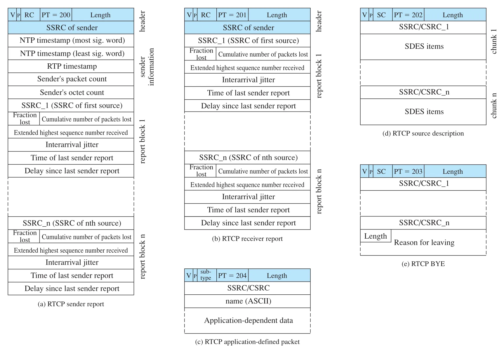 Figure 24.14 · PDF p. 847 · RTCP Sender Report, Receiver Report, SDES, Application-defined packet, BYE packet format
각 RTCP packet type은 공통적으로 32-bit word로 시작한다.
| RTCP common field | 크기 | 의미 |
|---|---|---|
Version | 2 bits | Current version. 원문 범위에서는 version 2 |
Padding | 1 bit | Control information 끝에 padding octets가 있는지 나타낸다. |
Count | 5 bits | SR/RR에서는 reception report block 수, SDES/BYE에서는 source item 수를 나타낸다. |
Packet Type | 8 bits | RTCP packet type을 식별한다. 예: SR=200, RR=201, SDES=202, BYE=203, APP=204 |
Length | 16 bits | Packet length in 32-bit words minus one |
SSRC | 32 bits | 이 RTCP packet source를 식별한다. SR/RR에 포함된다. |
Sender Report와 Receiver Report
Sender Report(SR)는 sender 역할도 하는 participant가 reception quality feedback을 제공할 때 사용한다. SR은 header, sender information block, zero or more reception report blocks로 구성된다.
Sender information block의 주요 field는 다음과 같다.
| SR sender info field | 의미 |
|---|---|
NTP Timestamp | Report가 전송된 absolute wall clock time. Receiver report의 timestamps와 함께 round-trip time 측정에 쓰일 수 있다. |
RTP Timestamp | RTP data packet timestamp 생성에 쓰인 relative time. Receiver가 report를 RTP data packets와 같은 time sequence에 배치할 수 있게 한다. |
Sender's Packet Count | 이 sender가 session에서 지금까지 전송한 RTP data packets 총수 |
Sender's Octet Count | 이 sender가 session에서 지금까지 전송한 RTP payload octets 총수 |
Reception report block은 이 participant가 data를 받은 각 source마다 하나씩 포함된다.
| Report block field | 의미 |
|---|---|
SSRC_n | 이 report block이 언급하는 source |
Fraction Lost | 직전 SR/RR 이후 해당 source의 RTP data packets 중 lost fraction |
Cumulative Number of Packets Lost | Session 동안 해당 source에서 lost된 RTP packets 총수 |
Extended Highest Sequence Number Received | 받은 highest RTP sequence number와 wraparound count를 함께 담는다. |
Interarrival Jitter | 해당 source의 RTP packets에서 관측한 jitter estimate |
Last SR Timestamp | 해당 source에서 마지막으로 받은 SR의 NTP timestamp 일부 |
Delay Since Last SR | 마지막 SR 수신부터 이 report block 전송까지의 delay. Last SR Timestamp와 함께 round-trip time estimation에 쓰인다. |
Receiver Report(RR)는 sender information block이 없다는 점을 제외하면 SR과 유사하다. 즉 data를 보내지 않는 participant도 reception quality feedback은 제공할 수 있다.
RTCP Jitter Estimate
앞에서 delay jitter를 single session에서 packet delay의 maximum variation으로 정의했지만, receiver에서 정확한 maximum variation을 간단히 측정하기는 어렵다. RTCP는 average interarrival jitter를 추정한다.
특정 source의 packet 에 대해 다음 값을 둔다.
| Symbol | 의미 |
|---|---|
| RTP data packet 의 timestamp | |
| Packet 의 arrival time을 RTP timestamp unit으로 표현한 값 | |
| Receiver에서 본 adjacent packet interarrival spacing과 source에서 본 adjacent packet generation spacing의 차이 | |
| Packet 수신 시점까지의 estimated average interarrival jitter |
계산식은 다음과 같다.
는 arrival spacing이 source spacing과 얼마나 다른지 측정한다. Jitter가 없으면 두 spacing이 같고 이다. 는 observed 의 exponential average라서 가장 최근 관측값에는 작은 weight만 준다. 이 덕분에 일시적 fluctuation 하나가 전체 estimate를 망가뜨리지 않는다.
SR/RR 값은 senders, receivers, network managers가 session condition을 monitoring하는 데 사용된다. Packet loss values는 persistent congestion을 나타내고, jitter는 transient congestion을 나타낼 수 있다. 특히 jitter increase는 packet loss로 이어지기 전 congestion warning이 될 수 있다.
SDES, BYE, Application-Defined Packet
SDES(Source Description) packet은 source가 자신에 관한 추가 정보를 제공한다. 각 chunk는 source 또는 contributing source identifier로 시작하고, 그 뒤에 descriptive items가 온다. 대표 SDES item은 CNAME, NAME, EMAIL, PHONE, LOC, TOOL, NOTE, PRIV 등이다. CNAME(Canonical name)은 하나의 RTP session 안에서 participants 사이에 unique한 canonical name을 제공한다.
BYE(Goodbye) packet은 하나 이상의 sources가 더 이상 active하지 않음을 나타낸다. Receiver는 long silence가 network failure가 아니라 departure 때문임을 알 수 있다. Mixer가 BYE packet을 받으면 source list를 그대로 유지해 forwarding한다. BYE packet에는 optional textual reason for leaving이 들어갈 수 있다.
Application-Defined Packet은 experimental use를 위한 packet이다. Application-specific functions/features를 시험하는 데 쓰이고, 일반적으로 유용하다고 판단되면 표준 RTCP packet type number를 배정받을 수 있다.
연결 관계
Chapter 24의 네 주제는 Internet multimedia stack의 서로 다른 층을 맡는다.
| 층/역할 | 관련 주제 | 핵심 기능 |
|---|---|---|
| Media representation | MPEG audio/video compression | Audio/video bit rate를 낮춰 network에 실을 수 있게 한다. |
| Traffic model | Real-time traffic | Delay, jitter, deadline, buffer, loss tolerance를 정의한다. |
| Session control | SIP + SDP | Participants를 찾고, availability/capability/session parameter를 협상한다. |
| Media transport | RTP | Timestamp, sequence number, payload type, source identifier로 real-time media packet을 운반한다. |
| Transport feedback/control | RTCP | QoS feedback, participant identification, session scaling, jitter/loss reports를 제공한다. |
SIP와 RTP의 역할 분리는 중요하다. SIP는 “누구와 어떤 session을 만들 것인가”를 해결하고, RTP는 “그 session에서 media packets를 어떤 timing/format/source 정보와 함께 보낼 것인가”를 해결한다. SDP는 이 둘 사이의 계약서처럼 media types, addresses, ports, payload types를 설명한다.
Compression과 real-time transport도 연결된다. MPEG compression은 network capacity 요구를 낮추지만, compressed video는 frame별 packet size가 달라지고 packet loss에 민감할 수 있다. RTP/RTCP는 이런 changing conditions를 payload type, timestamp, sequence number, receiver feedback으로 application이 인식하고 대응할 수 있게 한다.
오해하기 쉬운 내용
| 오해 | 바로잡기 |
|---|---|
| Real-time traffic은 무조건 TCP가 가장 안전하다. | TCP retransmission은 reliability에는 좋지만, 늦게 도착한 data가 real-time playback deadline을 넘으면 쓸모없을 수 있다. |
| UDP만 쓰면 RTP가 필요 없다. | UDP는 port addressing만 제공하고 timing, sequencing, payload type, source identification, feedback을 제공하지 않는다. |
| RTP가 hard real-time guarantee를 제공한다. | RTP는 soft real-time communication에 적합하며 deterministic jitter bound나 zero-loss guarantee를 제공하지 않는다. |
| SIP가 media packet을 직접 운반한다. | SIP는 session control protocol이고, media transport는 보통 RTP가 담당한다. |
| RTP Timestamp와 Sequence Number는 같은 역할이다. | Sequence Number는 packet ordering/loss detection, Timestamp는 media timing/playback reconstruction을 위한 값이다. |
| RTCP는 data 전송 protocol이다. | RTCP는 RTP data transfer에 대한 control/feedback protocol이다. User media data는 RTP가 운반한다. |
| Lossy compression은 항상 품질이 나쁘다. | Human perception 특성을 이용하면 눈/귀로 구분하기 어려운 정보를 줄여 큰 compression gain을 얻을 수 있다. |
핵심 용어 정리
| Term | 정리 |
|---|---|
lossless compression | Decompressed data가 original과 동일한 compression |
lossy compression | Decompressed data가 fidelity criterion을 만족하는 approximation이 되는 compression |
MPEG | Digital video/audio compression과 related system format을 다루는 표준 계열 |
simultaneous auditory masking | 강한 sound가 가까운 약한 sound를 perception에서 가리는 현상 |
DCT(Discrete Cosine Transform) | Pixel block을 frequency-domain-like coefficients로 바꾸는 video compression 단계 |
motion compensation | Frame 사이 유사 block을 motion vector와 prediction error로 표현하는 interframe compression 기법 |
I frame | 독립적으로 decode 가능한 intraframe-coded picture |
P frame | preceding I/P anchor frame을 참조하는 predicted frame |
B frame | preceding/following I/P frames를 참조하는 bidirectionally interpolated frame |
delay jitter | Session 안 packet delay variation의 최대 차이 또는 RTCP에서 추정하는 interarrival variation |
hard real-time | Zero loss tolerance와 deterministic upper bound가 중요한 real-time application |
soft real-time | 일부 loss/misordering을 tolerate할 수 있는 real-time application |
SIP(Session Initiation Protocol) | Real-time session setup/modification/termination을 위한 application-level control protocol |
SDP(Session Description Protocol) | SIP message body에서 media streams, addresses, ports, payload types 등을 설명하는 protocol |
VoIP(voice over IP) | IP network 위에서 voice communication을 제공하는 Internet telephony |
SIP proxy server | 다른 client를 대신해 request를 routing/forwarding하는 SIP intermediary |
SIP redirect server | UAC가 alternate URI에 contact하도록 redirect information을 제공하는 SIP server |
SIP registrar | REGISTER request를 받아 SIP address/IP address 정보를 location service에 저장하는 server |
RTP(Real-Time Transport Protocol) | Real-time media data에 sequence, timestamp, payload/source information을 붙여 전송하는 protocol framework |
RTCP(RTP Control Protocol) | RTP session의 QoS feedback, identification, scaling, control information을 제공하는 protocol |
SSRC(Synchronization Source Identifier) | RTP session 안에서 synchronization source를 식별하는 random value |
CSRC(Contributing Source Identifier) | Mixer가 RTP payload에 기여한 sources를 표시하는 identifier |
mixer | 여러 RTP streams를 결합해 새로운 stream을 만드는 RTP relay |
translator | RTP packet format/data rate/protocol domain을 변환하거나 packet을 복제하는 RTP relay |
면접 질문
lossless compression과lossy compression의 차이는 무엇이고, multimedia에서 lossy compression이 자주 쓰이는 이유는 무엇인가?- MPEG audio compression이
simultaneous auditory masking을 이용하는 방식은 무엇인가? - MPEG video에서
I frame,P frame,B frame은 각각 어떤 dependency를 가지는가? motion vector와prediction error는 interframe compression에서 각각 무엇을 표현하는가?- Real-time traffic에서
delay jitter가 playback buffer 크기와 packet discard에 어떤 영향을 주는가? hard real-time과soft real-timeapplication의 network design priority는 어떻게 다른가?- SIP에서
proxy server,redirect server,registrar,location service의 역할을 구분해 설명하라. - SIP와 SDP, RTP의 역할을 session setup과 media transport 관점에서 구분하라.
- TCP/UDP만으로 real-time multimedia transport가 부족한 이유는 무엇이며, RTP는 무엇을 추가로 제공하는가?
- RTP의
Sequence Number,Timestamp,Payload Type,SSRC는 각각 어떤 문제를 해결하는가? RTCP Sender Report와Receiver Report가 제공하는 feedback은 congestion/jitter/loss 판단에 어떻게 쓰이는가?