Chapter 2. The Internet Address Architecture
- 과목: Computer Network
- 기준 교재: TCP/IP Illustrated, Volume 1
- 관련 페이지: PDF pp. 70-117
- 우선순위: 필수
개요
이 장은 Internet의 network-layer address인 IP address가 어떤 구조를 갖고, 어떻게 표현되고, 어떻게 allocation/assignment되며, routing scalability와 어떤 관계를 갖는지 정리한다. IP router의 forwarding은 destination IP address를 보고 이루어지고, source IP address는 traffic이 어디서 왔는지 나타내는 단서가 된다. 따라서 IP address는 단순한 번호가 아니라 Internet topology, administrative hierarchy, routing table size, security 문제까지 연결하는 중심 구조다.
DNS가 정상적으로 동작하면 사용자는 보통 name을 쓰고 IP address를 직접 보지 않는다. 하지만 network setup, DNS failure, routing/debugging, subnet 설계에서는 IP address의 binary structure와 prefix 의미를 알아야 한다. IPv4와 IPv6는 address 길이와 표현 방식이 다르지만, 둘 다 interface를 식별하고 forwarding decision의 기반이 된다는 공통점을 갖는다.
핵심 개념
- IP address: Internet Protocol에서 interface 또는 addressable endpoint를 식별하는 network-layer address다. IPv4는 32-bit, IPv6는 128-bit다.
- dotted-quad / dotted-decimal notation: IPv4 32-bit 값을 8-bit씩 네 부분으로 나누어
165.195.130.107처럼 decimal로 쓰는 방식이다. - IPv6 colon-hex notation: IPv6 128-bit 값을 16-bit block 8개로 나누어 hexadecimal과 colon으로 쓰는 방식이다.
- prefix: address의 앞쪽 contiguous bits로, routing과 network/subnetwork 식별에 쓰인다.
- unicast / broadcast / multicast / anycast: address가 단일 interface, 전체 network, group, 또는 가장 가까운 member 중 하나를 가리키는지에 따른 address 의미다.
- classful addressing: IPv4 초기에 fixed class A/B/C/D/E로 address space를 나누던 방식이다. 현재 routing 설계의 역사적 배경이다.
세부 정리
2.1 Introduction
IP address는 host와 router가 Internet에서 traffic을 주고받는 위치 정보를 제공한다. 모든 Internet-connected device는 적어도 하나의 IP address를 갖고, private TCP/IP network의 device도 내부 중복을 피하도록 address를 조정해야 한다. global Internet에서는 address가 중복되면 forwarding ambiguity가 생기므로 allocation이 administrative hierarchy를 통해 관리된다.
주소 관리에는 allocation과 assignment를 구분하는 것이 중요하다. allocation은 address block을 user, organization, ISP 같은 주체에게 나누어 주는 것이고, assignment는 받은 address를 실제 device/interface에 붙이는 것이다. 보통 개인 사용자는 ISP로부터 address allocation 또는 assignment를 받고, ISP는 그 address들로 들어오는 traffic을 routing해 주겠다는 약속까지 함께 제공한다.
2.2 Expressing IP Addresses
IPv4 address는 32-bit nonnegative integer이지만, 사람이 읽기 쉽게 dotted-quad notation으로 표현한다. 각 decimal component는 8-bit octet 하나이므로 범위는 0-255다. 예를 들어 165.195.130.107은 binary로 10100101 11000011 10000010 01101011에 대응한다. subnet, prefix, mask를 이해할 때는 이 dotted notation 뒤에 있는 binary bit layout이 실제 기준이다.
IPv6 address는 128-bit라서 decimal dotted notation이 너무 길다. 표준 표현은 16-bit field 8개를 hexadecimal로 쓰고 colon으로 구분하는 colon-hex notation이다. 예를 들어 5f05:2000:80ad:5800:0058:0800:2023:1d71처럼 쓴다.
IPv6 표현에는 축약 규칙이 있다. 첫째, 각 block의 leading zeros는 생략할 수 있다. 둘째, all-zero block의 연속은 ::로 한 번만 줄일 수 있다. 예를 들어 0:0:0:0:0:0:0:1은 ::1, 2001:0db8:0:0:0:0:0:2는 2001:db8::2가 된다. ::는 한 address 안에서 한 번만 쓸 수 있는데, 두 번 쓰면 생략된 zero block 길이를 역으로 결정할 수 없어 ambiguity가 생긴다.
IPv6 안에 IPv4 주소를 표현하는 방식도 있다. ::ffff:10.0.0.1은 IPv4-mapped IPv6 address로, IPv4 address 10.0.0.1을 IPv6 address 형태에 담아 software가 IPv4/IPv6 address를 함께 다루기 쉽게 한다. 반면 ::1.2.240.1 또는 ::102:f001 같은 IPv4-compatible IPv6 address는 과거 transition 계획에서 쓰였지만 현재는 더 이상 필요하지 않은 방식이다. 둘은 이름이 비슷하지만 의미가 다르다.
URL에서 IPv6 literal을 쓸 때는 port number의 colon과 IPv6 block separator colon이 충돌할 수 있다. 그래서 http://[2001:0db8:85a3:08d3:1319:8a2e:0370:7344]:443/처럼 IPv6 address를 square brackets []로 감싼다.
RFC5952는 같은 IPv6 address가 너무 많은 방식으로 표현되는 문제를 줄이기 위해 canonical text representation 규칙을 제안한다. leading zeros는 반드시 제거하고, ::는 가능한 가장 긴 zero run에 최대한 사용하며, 길이가 같은 zero run이 여럿이면 첫 번째를 줄이고, hexadecimal a-f는 lowercase로 쓴다.
2.3 Basic IP Address Structure
IPv4 address space는 2^32 = 4,294,967,296개 address를 갖고, IPv6 address space는 2^128개 address를 갖는다. 이 거대한 공간은 type과 size에 따라 block으로 나뉜다. 대부분의 IPv4 address space는 unicast address로 interface 하나를 식별하는 데 사용되어 왔다. 그 밖에 broadcast, multicast, anycast, special-purpose address처럼 하나 이상의 interface나 특정 의미를 갖는 address가 있다.
2.3.1 Classful Addressing
초기 IPv4 unicast address는 network portion과 host portion으로 나뉘었다. network portion은 해당 interface가 속한 network를, host portion은 그 network 안의 특정 host/interface를 식별한다. 당시에는 대부분의 host가 network interface를 하나만 갖고 있었기 때문에 interface address와 host address라는 말을 거의 섞어 썼다.
classful addressing은 network 규모가 서로 다르다는 점을 반영해 IPv4 address space를 A, B, C, D, E class로 나누었다. Class A/B/C는 unicast address allocation에 사용되었고, Class D는 multicast, Class E는 reserved 용도다. Class는 address의 맨 앞 bit pattern으로 결정된다. Class A는 leading bit 0, Class B는 10, Class C는 110, Class D는 1110, Class E는 1111로 시작한다.
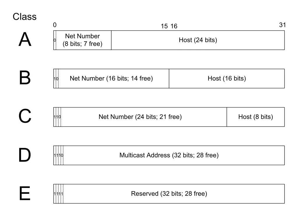
Figure 2-1 · PDF p. 74 · IPv4 classful address space에서 network/host bit가 class별로 나뉘는 방식
Figure 2-1은 classful addressing의 핵심 trade-off를 보여준다. Class A는 network number가 작고 host number가 커서 매우 큰 network에 맞지만 allocation 단위가 과하게 크다. Class C는 network number가 크고 host number가 작아 작은 network에 맞지만 큰 조직에는 너무 작다. 이런 fixed-size class 구조는 address 낭비와 routing scalability 문제를 낳았고, 뒤의 subnetting, VLSM, CIDR이 등장하는 배경이 된다.
classful IPv4 partition은 대략 다음 의미를 가진다.
| Class | Address range | High-order bits | 원래 용도 | 구조적 문제 |
|---|---|---|---|---|
| A | 0.0.0.0-127.255.255.255 | 0 | 매우 큰 unicast network | class A network 수가 너무 적고 allocation 단위가 과대 |
| B | 128.0.0.0-191.255.255.255 | 10 | 중간 규모 unicast network | 많은 site에는 여전히 과대, 큰 site에는 때로 부족 |
| C | 192.0.0.0-223.255.255.255 | 110 | 작은 unicast network | host 수가 256개라 큰 site에는 부족 |
| D | 224.0.0.0-239.255.255.255 | 1110 | multicast | unicast allocation 아님 |
| E | 240.0.0.0-255.255.255.255 | 1111 | reserved | 일반 unicast 사용 아님 |
Class A/B/C의 host 수는 표면상 각각 2^24, 2^16, 2^8개지만, 보통 range의 첫 address와 마지막 address는 unicast host address로 쓰지 않는다. 예를 들어 18.0.0.0/8 같은 class A allocation은 이론상 2^24개 address를 담지만 실제 host에 할당 가능한 수는 보통 2^24 - 2로 본다. 이 “첫/마지막 address 제외” 관례는 subnet broadcast 설명에서 다시 중요해진다.
2.3.2 Subnet Addressing
subnet addressing은 중앙에서 받은 class A/B/C network number를 site 내부에서 다시 여러 subnet으로 나누는 방식이다. 핵심 목적은 새 LAN segment가 생길 때마다 global Internet의 중앙 authority에서 새 network number를 받을 필요 없이, site administrator가 local numbering plan을 구성할 수 있게 하는 것이다.
subnetting은 IPv4 address 길이를 늘리지 않는다. 대신 원래 host portion으로 쓰였던 bit 일부를 subnet number로 재해석한다. 따라서 address 구조는 network number + subnet ID + host ID가 된다. 이 추가 구분은 site 내부 router와 host만 알면 되고, site 밖 Internet은 여전히 전통적인 classful network number만 보고 해당 site의 border router로 traffic을 보낸다.
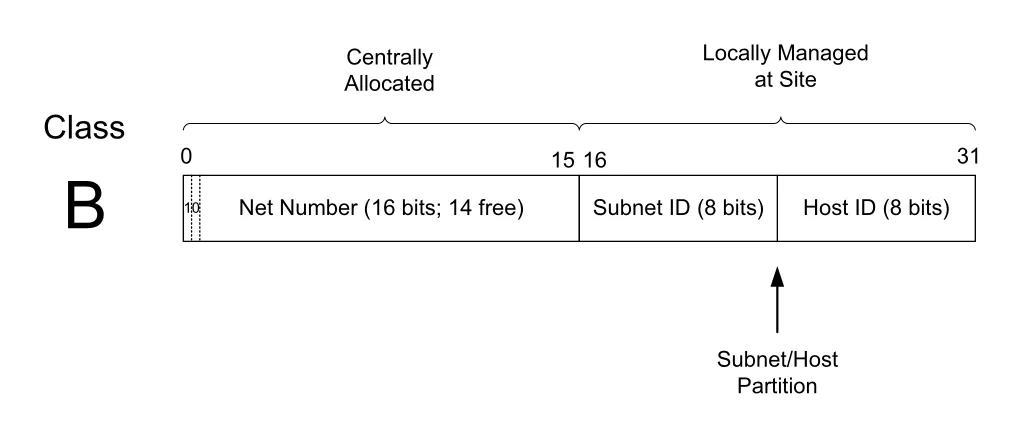
Figure 2-2 · PDF p. 76 · class B address의 host portion을 subnet ID와 host ID로 나누는 예
Figure 2-2의 예에서 class B network는 앞 16 bits가 centrally allocated network number다. 남은 16 bits 중 8 bits를 subnet ID로 쓰면 2^8 = 256개 subnet을 만들 수 있고, 각 subnet에는 host ID 8 bits가 남는다. 각 subnet에서 all-zero host와 all-one host를 제외하면 2^8 - 2 = 254개 host address를 쓸 수 있다. 더 많은 subnet을 원하면 host 수를 줄이고, 더 많은 host를 원하면 subnet 수를 줄이는 trade-off가 생긴다.
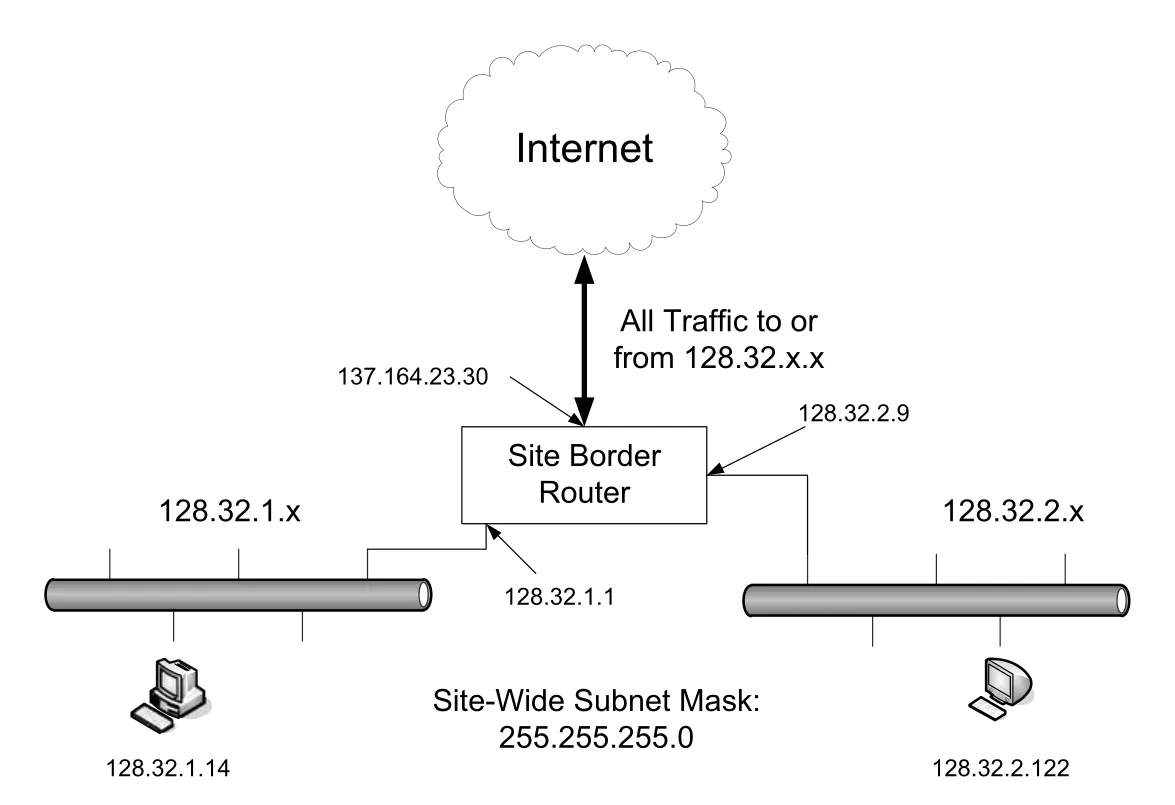
Figure 2-3 · PDF p. 77 · `128.32.0.0` class B site가 `255.255.255.0` mask로 내부 subnet을 나누는 구조
Figure 2-3은 site 밖과 site 안의 관점 차이를 보여준다. Internet routing system은 128.32.x.x로 가는 모든 traffic을 site border router로 보낸다. 하지만 border router는 내부에서 128.32.1.x와 128.32.2.x가 서로 다른 subnet이라는 사실을 알아야 한다. 이 local distinction을 가능하게 하는 configuration parameter가 subnet mask다.
2.3.3 Subnet Masks
subnet mask는 IP address에서 network/subnetwork portion과 host portion의 경계를 알려주는 bit mask다. IPv4 mask는 32-bit, IPv6 mask는 128-bit이며, 일반적으로 왼쪽부터 contiguous 1 bits가 오고 그 뒤에 0 bits가 온다. 1인 bit position은 forwarding에 쓰이는 network/subnetwork part이고, 0인 bit position은 host part다.
IPv4 subnet mask는 dotted-decimal로 255.255.255.0처럼 쓸 수도 있고, contiguous 1 bits의 개수만 적는 prefix length로 /24처럼 쓸 수도 있다. 오늘날에는 prefix length notation이 가장 흔하다. 예를 들어 255.255.254.0은 /23, 255.255.255.192는 /26, 255.255.255.255는 /32다. IPv6에서도 같은 원리로 ffff:ffff:ffff:ffff::는 /64, ff00::는 /8이다.
mask를 적용해 prefix를 구할 때는 bitwise AND를 사용한다.
address: 128.32.1.14
mask:    255.255.255.0  (/24)
AND 결과: 128.32.1.0   → prefix 128.32.1.0/24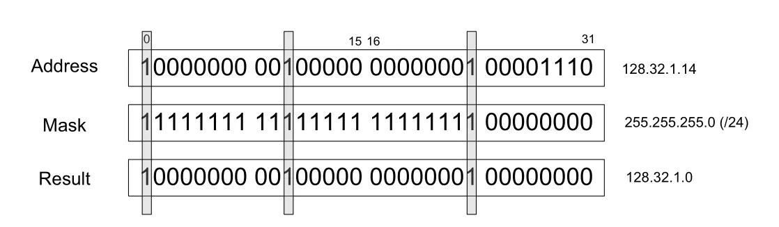
Figure 2-4 · PDF p. 79 · IP address와 subnet mask를 bitwise AND하여 routing prefix를 얻는 과정
subnet mask는 local matter다. Figure 2-3의 외부 Internet router들은 128.32 class B network로만 route하면 되고, site 내부의 /24 subnet 구분을 알 필요가 없다. 반대로 site border router와 내부 host/router는 정확한 mask를 알아야 128.32.1.14를 128.32.1.0/24 subnet에 속한 address로 판단할 수 있다.
2.3.4 Variable-Length Subnet Masks (VLSM)
VLSM(Variable-Length Subnet Masks)은 같은 site의 같은 base network number 안에서 서로 다른 subnet mask length를 사용하는 방식이다. 모든 subnet을 같은 크기로 나누면 관리가 단순하지만, 작은 point-to-point link와 큰 LAN이 같은 address block 크기를 소비해 낭비가 생긴다. VLSM은 subnet마다 host 수 요구가 다를 때 address utilization을 개선한다.
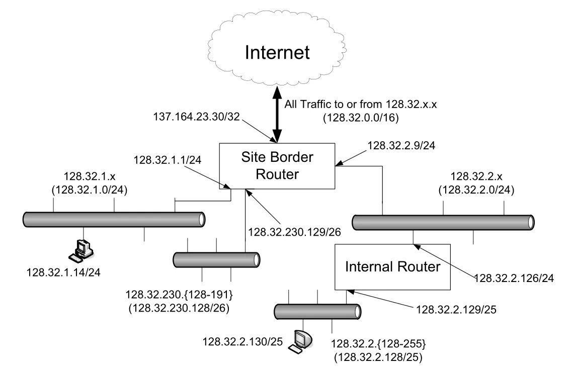
Figure 2-5 · PDF p. 80 · 하나의 `128.32.0.0/16` site 안에서 `/24`, `/25`, `/26` subnet을 함께 쓰는 VLSM 예
Figure 2-5에서는 128.32.0.0/16 내부에 /24, /25, /26 subnet이 함께 있다. /24는 host part가 8 bits라 256개 address를 담고, /25는 7 bits라 128개, /26은 6 bits라 64개 address를 담는다. host와 router의 각 interface는 IP address뿐 아니라 해당 subnet mask도 함께 설정되어야 한다. OSPF, IS-IS, RIPv2 같은 classless-aware dynamic routing protocol은 이런 prefix length 정보를 전달할 수 있지만, RIP version 1처럼 오래된 protocol은 VLSM을 제대로 지원하지 못한다.
point-to-point router link처럼 양 끝에 두 interface만 있는 subnet은 더 작은 prefix가 유리하다. IPv4에서는 /31, IPv6에서는 /127 prefix를 사용하는 것이 가능하고 권장된다. 예전의 “network address와 broadcast address 때문에 항상 host address 두 개를 빼야 한다”는 직관은 point-to-point 특수 case에서는 달라질 수 있다.
2.3.5 Broadcast Addresses
IPv4 subnet에는 subnet broadcast address가 있다. 이는 해당 subnet의 모든 host에게 datagram을 보내기 위한 address로, network/subnetwork portion은 해당 prefix 값으로 두고 host field의 모든 bit를 1로 설정해 만든다. 예를 들어 128.32.1.0/24 subnet의 broadcast address는 128.32.1.255다.
broadcast address는 subnet mask의 complement와 address 또는 prefix를 bitwise OR하여 계산할 수 있다.
address:          128.32.1.14
mask complement:    0.0.0.255
OR 결과:          128.32.1.255  → subnet broadcast address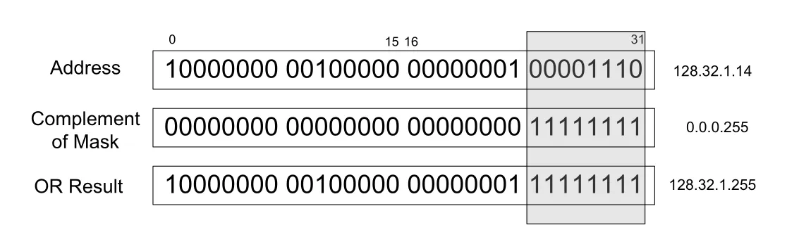
Figure 2-6 · PDF p. 81 · subnet mask의 complement와 address를 OR하여 subnet broadcast address를 만드는 과정
directed broadcast는 subnet broadcast address를 destination으로 한 datagram이 Internet을 통해 target subnet까지 route된 뒤, 그 subnet에서 all-host broadcast로 전달되는 개념이다. 예를 들어 128.32.1.255는 128.32.1.0/24 subnet의 directed broadcast이고, 더 크게 128.32.255.255는 Figure 2-3/2-5의 site 전체를 겨냥하는 broadcast처럼 해석될 수 있다.
하지만 directed broadcast forwarding은 security 문제 때문에 오늘날 Internet에서는 기본적으로 disabled다. 공격자가 source를 spoofing하고 directed broadcast를 증폭 지점으로 쓰면 여러 host가 피해자에게 응답하게 만드는 amplification attack이 가능하기 때문이다. 반면 255.255.255.255는 local net broadcast 또는 limited broadcast로, router가 forward하지 않는다. 같은 link 안에서는 link-layer broadcast mechanism을 통해 동작할 수 있지만, router를 넘어가지 않는다.
IPv6에는 broadcast address가 없다. IPv4에서 broadcast를 쓰던 많은 자리는 IPv6에서 multicast address로 대체된다. 이 차이는 IPv6가 “모두에게 뿌리는” broadcast 대신 scope와 group semantics를 갖는 multicast를 더 중심 구조로 삼는다는 뜻이다.
2.3.6 IPv6 Addresses and Interface Identifiers
IPv6 address는 IPv4보다 4배 긴 128-bit address일 뿐 아니라 scope 구조를 포함한다. scope는 address가 유효하게 사용될 수 있는 network 범위를 뜻한다. node-local은 같은 computer 안에서만, link-local은 같은 link 또는 IPv6 prefix 내에서만, global은 Internet-wide communication에 사용된다. IPv6 node는 보통 하나의 interface에도 여러 address를 가진다. IPv4에서도 여러 address를 붙일 수 있지만 IPv6에서는 훨씬 일반적인 operating model이다.
site-local prefix fec0::/10은 과거 IPv6 unicast scope로 제안되었지만 deprecated되었다. 같은 address가 여러 site에서 재사용될 수 있고, site의 경계를 명확히 정의하기 어렵다는 문제가 있었기 때문이다. 이 배경은 IPv6 private/local address 설계가 단순히 IPv4 private address를 길게 늘린 문제가 아니라는 점을 보여준다.
IPv6의 link-local address와 일부 global address는 interface identifier(IID)를 low-order bits로 사용한다. IID는 같은 network prefix 안에서 unique해야 하며, 보통 64 bits 길이다. IID는 network interface의 link-layer MAC address를 기반으로 modified EUI-64 형식에서 만들 수도 있고, privacy를 위해 randomized value로 만들 수도 있다. 후자는 address tracking을 줄이기 위한 설계와 연결된다.
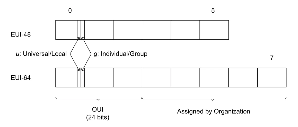
Figure 2-7 · PDF p. 83 · EUI-48/EUI-64 구조와 IPv6 interface identifier 생성에 쓰이는 bit 의미
EUI(Extended Unique Identifier)는 IEEE가 정의한 interface identifier 형식이다. EUI-48과 EUI-64는 앞 24 bits에 OUI(Organizationally Unique Identifier)를 담고, 나머지는 해당 organization이 assigned한다. 첫 byte의 low-order bit 중 u bit는 universal/local administration을, g bit는 individual/group address를 나타낸다.
EUI-48 MAC address에서 EUI-64를 만들 때는 OUI 24 bits 뒤에 FFFE를 삽입하고 나머지 24 bits를 붙인다. 예를 들어 00-11-22-33-44-55는 00-11-22-FF-FE-33-44-55가 된다. IPv6 modified EUI-64 IID는 여기서 u bit를 invert한다.
Linux 예시에서 Ethernet hardware address 00:30:48:2A:19:89는 먼저 00:30:48:ff:fe:2a:19:89로 EUI-64가 되고, u bit inversion 후 02:30:48:ff:fe:2a:19:89 IID가 된다. 여기에 link-local prefix fe80::/10을 붙이면 fe80::230:48ff:fe2a:1989/64 같은 IPv6 link-local address가 만들어진다.
interface에 EUI-48 같은 hardware identifier가 없으면, 다른 underlying address를 zero-padding하거나 같은 node의 다른 interface identifier에서 유도하거나, 마지막 수단으로 manual assignment를 사용할 수 있다. tunnel interface의 경우 ISATAP처럼 IPv4 address를 embedded value로 사용해 fe80::5efe:10.153.141.135 같은 link-local IPv6 address를 만들 수 있다. Windows의 %2 같은 suffix는 zone ID로, 같은 link-local prefix가 여러 interface에 있을 때 어떤 interface의 address인지 구분한다.
2.4 CIDR and Aggregation
subnet addressing으로 site 내부 확장 문제는 완화되었지만, 1990년대 초 Internet은 더 큰 scaling problem을 맞았다. class B address space 고갈, 32-bit IPv4 address space 부족 전망, global routing table entry 증가가 동시에 문제가 되었다. IETF의 ROAD(ROuting and ADdressing) group은 단기적으로 classful boundary를 제거하고 hierarchical aggregation을 촉진하는 방향을 제안했다. 장기적 주소 공간 부족은 IPv6가 다루도록 설계되었다.
2.4.1 Prefixes
CIDR(Classless Inter-Domain Routing)은 class A/B/C라는 고정 경계를 없애고, 임의 길이의 prefix와 mask로 address block을 표현하는 방식이다. classful 방식에서는 class B 하나가 너무 크고 class C 여러 개가 routing table을 키우는 문제가 있었다. CIDR은 more than 255 but fewer than 65,536 hosts 같은 중간 크기 address range를 편하게 allocate할 수 있게 한다.
CIDR mask는 subnet mask와 비슷하지만 site 내부에서만 쓰이는 local matter가 아니다. global Internet routing system의 core router도 prefix length를 해석하고 처리해야 한다. 따라서 CIDR의 network prefix는 address management와 inter-domain routing 모두의 기본 단위가 된다.
prefix notation은 base address/prefix length 형식이다. IPv4 prefix length는 0-32, IPv6 prefix length는 0-128 범위다. /0은 아무 bit도 고정하지 않으므로 전체 address space를 뜻하고, IPv4 /32는 단일 address를 뜻한다. 예를 들어 198.128.128.192/27은 앞 27 bits가 고정된 32개 address range를, 2001:db8::/32는 앞 32 bits가 2001:db8인 IPv6 block을 뜻한다.
classful network도 prefix notation으로 일반화할 수 있다. class A는 /8, class B는 /16, class C는 /24로 표현할 수 있다. 중요한 변화는 이제 prefix length가 class의 leading bits에서 자동으로 결정되지 않고, routing/assignment 정보에 명시되어야 한다는 점이다.
2.4.2 Aggregation
CIDR이 다양한 block size allocation을 가능하게 했지만, 그것만으로 routing table entry 수를 줄이지는 못한다. router는 destination IP address를 보고 matching routing table entry를 찾고, 그 entry에서 next hop을 얻는다. destination이 많을수록 모든 router가 들고 있어야 할 routing state가 커진다.
hierarchical routing의 핵심 아이디어는 topology에 맞게 address를 배치하면 routing state를 줄일 수 있다는 것이다. network가 tree-like topology이고 address도 location-sensitive하게 할당되면, 상위 router는 하위 모든 node를 개별 entry로 기억하지 않고 큰 prefix 몇 개만 기억해도 된다.
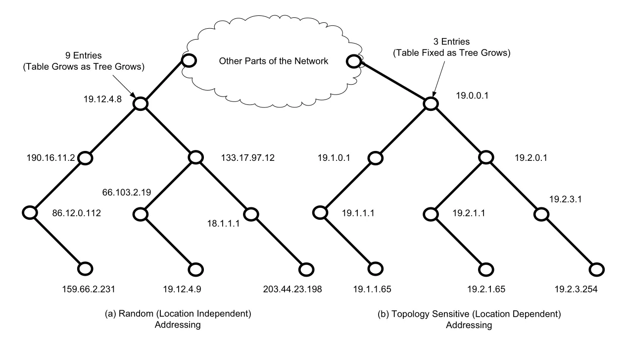
Figure 2-8 · PDF p. 88 · topology-sensitive addressing이 routing table state를 줄이는 방식
Figure 2-8의 왼쪽처럼 address가 topology와 무관하게 random하게 배치되면 root router는 아래 router 각각에 대한 entry를 많이 가져야 shortest-path routing을 유지할 수 있다. 오른쪽처럼 왼쪽 subtree는 19.1 prefix, 오른쪽 subtree는 19.2 prefix로 묶이면 root router는 19.1로 가는 next hop, 19.2로 가는 next hop, 나머지 network로 가는 default-like entry 정도만 갖고도 된다. trade-off는 address assignment가 topology에 민감해진다는 점이다. topology가 크게 바뀌면 address renumbering이 필요할 수 있다.
route aggregation은 여러 numerically adjacent IP prefixes를 더 짧은 하나의 prefix, 즉 aggregate 또는 summary로 합치는 절차다. aggregate는 더 넓은 address space를 cover하지만, routing table entry 수를 줄인다. 단, arbitrary prefix를 아무렇게나 합칠 수 있는 것은 아니고, binary boundary와 adjacency가 맞아야 한다.
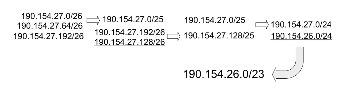
Figure 2-9 · PDF p. 89 · numerically adjacent prefix들을 더 짧은 aggregate prefix로 합치는 과정
Figure 2-9에서 190.154.27.0/26과 190.154.27.64/26은 인접하므로 190.154.27.0/25로 aggregate될 수 있다. 하지만 190.154.27.192/26은 처음 두 prefix와 바로 맞물리지 않으므로 첫 단계에서는 합칠 수 없다. 이후 190.154.27.128/26이 추가되면 190.154.27.128/25가 만들어지고, 이것이 기존 190.154.27.0/25와 합쳐져 190.154.27.0/24가 된다. 여기에 adjacent한 190.154.26.0/24까지 있으면 최종적으로 190.154.26.0/23이 된다.
aggregation은 routing scalability의 핵심이지만 정확성의 비용이 있다. aggregate가 실제로 모두 같은 next hop 뒤에 있는 address block을 대표할 때 가장 효과적이다. 그렇지 않으면 더 specific prefix가 필요해지고, router는 longest prefix match로 더 긴 prefix를 우선 적용해야 한다. 이 점은 Chapter 5의 forwarding/routing table lookup으로 이어진다.
2.5 Special-Use Addresses
IPv4와 IPv6 address space에는 일반 unicast assignment에 쓰지 않는 special-use address range가 있다. 이 range들은 local communication, private network, documentation, loopback, link-local, multicast, transition mechanism, reserved space처럼 특정 semantic을 가진다.
중요한 IPv4 special-use address는 다음처럼 이해하면 된다.
| Prefix | 의미 | 핵심 주의점 |
|---|---|---|
0.0.0.0/8 | local network의 host를 나타내는 source 용도 | 일반 destination으로 쓰는 address가 아니다 |
10.0.0.0/8, 172.16.0.0/12, 192.168.0.0/16 | private network address | public Internet에서 route되지 않으며 NAT와 자주 함께 쓰인다 |
127.0.0.0/8 | loopback | 보통 127.0.0.1이 local host test에 쓰인다 |
169.254.0.0/16 | IPv4 link-local | DHCP 없이 자동 구성될 수 있고 한 link 밖으로 route되지 않는다 |
192.0.2.0/24, 198.51.100.0/24, 203.0.113.0/24 | TEST-NET documentation | 예제용 address로 public Internet에 나타나면 안 된다 |
224.0.0.0/4 | IPv4 multicast | destination address로만 사용 |
255.255.255.255/32 | limited broadcast | router가 forward하지 않는다 |
IPv6에서도 ::/128 unspecified address, ::1/128 loopback, ::ffff:0:0/96 IPv4-mapped address, 2001:db8::/32 documentation prefix, fc00::/7 unique local unicast, fe80::/10 link-local unicast, ff00::/8 multicast 같은 special-use prefix가 있다. 공통 원칙은 special/multicast/reserved가 아닌 address space가 일반 unicast assignment 후보라는 점이다.
private/nonroutable address는 local administrative decision으로 관리된다. IPv4 private address는 home network와 enterprise internal network에서 흔하고, public Internet으로 나갈 때 NAT(Network Address Translation)가 IP datagram 내부 address를 rewriting하는 방식과 자주 결합된다. NAT는 Chapter 7에서 더 자세히 다룬다.
2.5.1 Addressing IPv4/IPv6 Translators
IPv4와 IPv6가 동시에 존재하는 network에서는 translator가 필요할 수 있다. unicast translation에서는 IPv4 address를 IPv6 address 안에 algorithmically embed하는 IPv4-embedded IPv6 address가 사용된다. 잘 알려진 prefix는 64:ff9b::/96이며, organization-specific prefix를 사용할 수도 있다.
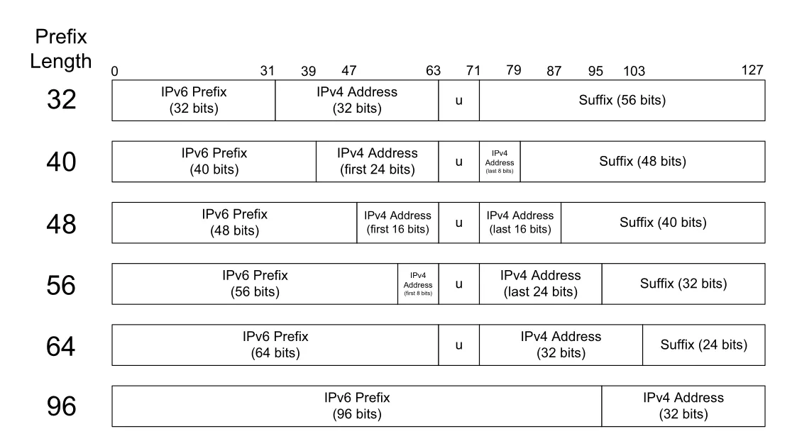
Figure 2-10 · PDF p. 92 · IPv6 prefix 길이에 따라 IPv4 address를 IPv6 address 안에 embed하는 형식
Figure 2-10의 형식은 IPv6 prefix length가 32, 40, 48, 56, 64, 96 중 하나일 때 IPv4 32-bit address를 어디에 넣는지 보여준다. 핵심 알고리즘은 IPv6 prefix와 IPv4 address를 concatenate하고, RFC4291 호환성을 위해 bits 64-71에 해당하는 u 위치를 0으로 유지하며, 남는 suffix bits를 0으로 채워 128-bit address를 만드는 것이다. /96 well-known prefix를 쓰면 IPv4 address 198.51.100.16은 64:ff9b::198.51.100.16처럼 표현될 수 있다.
2.5.2 Multicast Addresses
IP multicast address는 single interface가 아니라 host interface group을 식별한다. group의 coverage는 scope라고 하며, node-local, link-local, site-local, global, administrative scope 등이 있다. administrative scope는 router가 boundary로 설정되어 multicast traffic이 특정 administrative region을 넘지 않게 하는 방식이다.
host의 protocol stack은 software control 아래 multicast group에 join하거나 leave할 수 있다. sender는 source address로 자기 unicast IP address를 넣고 destination address로 multicast group address를 넣어 datagram을 보낸다. scope 안에서 group에 join한 host들이 datagram을 받아야 하지만, sender는 일반적으로 누가 몇 명이나 받는지 모른다.
ASM(any-source multicast)은 어떤 sender든 group으로 보낼 수 있고 receiver는 group address만 지정해 join하는 model이다. SSM(source-specific multicast)은 group address와 source IP address를 함께 channel로 지정해 단일 sender 중심으로 multicast를 구성한다. SSM은 ASM deployment의 복잡성을 줄이려는 방향이며, wide-area multicast가 널리 보급되지 못한 배경을 이해하는 데 중요하다.
2.5.3 IPv4 Multicast Addresses
IPv4 multicast는 class D range 224.0.0.0-239.255.255.255, 즉 224.0.0.0/4를 사용한다. 28 bits가 group 식별에 쓰일 수 있으므로 이론적으로 많은 host group을 표현할 수 있다. 다만 전체 range가 하나의 평평한 pool처럼 쓰이는 것이 아니라 routing/administration 목적에 따라 여러 block으로 나뉜다.
IPv4 multicast에서 특히 기억할 block은 다음과 같다.
| Range | 의미 |
|---|---|
224.0.0.0-224.0.0.255 | local network control, multicast router가 forward하지 않음. 224.0.0.1 All Hosts group 포함 |
224.0.1.0-224.0.1.255 | internetwork control, 필요하면 local link 밖으로 forwarded |
232.0.0.0/8 | SSM(source-specific multicast) |
233.0.0.0/8 일부 | GLOP, AS number 기반 multicast address allocation |
234.0.0.0/8 | UBM(unicast-prefix-based multicast) |
239.0.0.0/8 | administrative scope, private unicast address의 multicast analog |
GLOP은 16-bit AS number를 IPv4 multicast address의 두 번째/세 번째 byte에 넣어 AS별 multicast address range를 만드는 방식이다. 간단하지만 16-bit AS number 제약과 granularity 문제가 있다.
UBM(unicast-prefix-based multicast addressing)은 이미 allocated된 unicast prefix를 기반으로 multicast address를 유도한다. /24 또는 그보다 짧은 unicast prefix를 받은 site는 234/8 prefix 뒤에 자기 unicast prefix와 group ID를 붙여 사용할 수 있다.
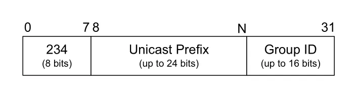
Figure 2-11 · PDF p. 95 · `234/8` prefix와 unicast prefix, group ID를 결합하는 IPv4 UBM address format
예를 들어 unicast prefix 192.0.2.0/24에는 UBM address 234.192.0.2가 대응된다. 234.128.32.0/24 multicast range는 left-shift하면 128.32.0.0/16 unicast allocation과 연결되므로, owner를 추적하기 쉽다. 이 방식은 별도 multicast allocation 절차를 줄이고, 기존 unicast allocation의 ownership 정보를 재사용한다.
administratively scoped multicast block은 multicast traffic의 배포 범위를 특정 router/host 집합 안으로 제한하는 데 쓰인다. private unicast address처럼 public Internet 전체로 내보내려는 용도가 아니며, enterprise boundary에서 차단되는 경우가 많다. 큰 site는 이 scope를 work group, division, geographic area처럼 내부 정책 단위로 더 나눌 수 있다.
2.5.4 IPv6 Multicast Addresses
IPv6는 IPv4보다 multicast를 더 적극적으로 사용한다. IPv6 multicast prefix는 ff00::/8이며, group number를 담는 데 112 bits가 남는다. IPv6에는 broadcast가 없기 때문에, neighbor discovery나 all-nodes/all-routers 같은 기능도 multicast 기반으로 설계된다.
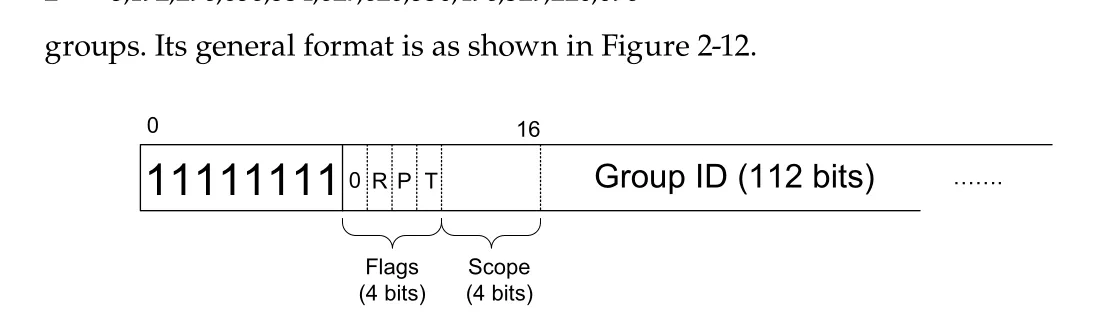
Figure 2-12 · PDF p. 96 · IPv6 multicast base format: Flags, Scope, Group ID
base IPv6 multicast address의 두 번째 byte는 4-bit Flags와 4-bit Scope ID를 포함한다. Flags의 핵심 bit는 R, P, T다. T는 transient group인지, P는 unicast prefix 기반 address인지, R은 rendezvous point(RP) 정보를 포함하는지를 나타낸다. Scope 값은 distribution boundary를 나타낸다. 대표적으로 1은 interface-local, 2는 link-local, 4는 admin-local, 5는 site-local, 8은 organization-local, e는 global scope다.
IPv6 multicast에는 scope-relative 또는 variable-scope address가 있다. 예를 들어 ff0x::101은 NTP servers를 가리키는데, x가 scope를 뜻하므로 ff02::101은 같은 link의 NTP server, ff0e::101은 global scope의 NTP server처럼 해석된다. 같은 group function이 scope만 달리해 여러 범위에서 재사용되는 구조다.
P bit가 1이면 unicast-prefix-based IPv6 multicast address가 된다. 이미 global하게 할당된 unicast prefix를 multicast address 안에 넣어, multicast group별 global allocation agreement를 줄인다.
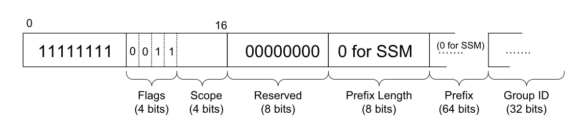
Figure 2-13 · PDF p. 98 · unicast prefix를 포함하는 IPv6 multicast address format
Figure 2-13의 format은 reserved field, prefix length, prefix, 32-bit group ID를 담는다. 예를 들어 organization이 3ffe:ffff:1::/48 unicast prefix를 받으면, ff3x:30:3ffe:ffff:1::/96 형태의 unicast-based multicast prefix도 사실상 사용할 수 있다. 여기서 x는 scope value다. SSM도 이 format을 활용하되 prefix length와 prefix fields를 0으로 두어 ff3x::/32 계열을 사용한다.
link-local 또는 node-local scope에서만 unique multicast가 필요하면 IID 기반 format을 쓸 수 있다. 이 방식은 router나 global prefix가 없는 ad hoc environment에서도 host가 자기 IID를 기반으로 unique multicast address를 만들 수 있게 한다.
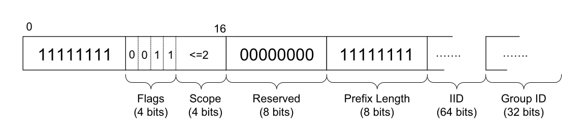
Figure 2-14 · PDF p. 98 · link-scoped IPv6 multicast에서 IID와 group ID를 결합하는 형식
Figure 2-14 format은 Figure 2-13과 비슷하지만 prefix 대신 64-bit IID를 담고, prefix length field가 특수 값으로 설정된다. 이 형식은 scope가 link-local 이하일 때만 적합하다. 더 넓은 scope가 필요하면 unicast-prefix-based allocation 또는 permanent multicast address를 사용해야 한다.
R bit는 multicast routing에서 rendezvous point(RP)를 찾기 쉽게 하기 위한 확장이다. RP는 PIM-SM 같은 multicast routing protocol에서 sender와 receiver가 같은 group을 찾도록 도와주는 router address다. Internet-wide multicast deployment에서 RP discovery가 어려운 문제였기 때문에, IPv6 multicast address 자체에 RP address 일부를 embed하는 방식이 제안되었다.
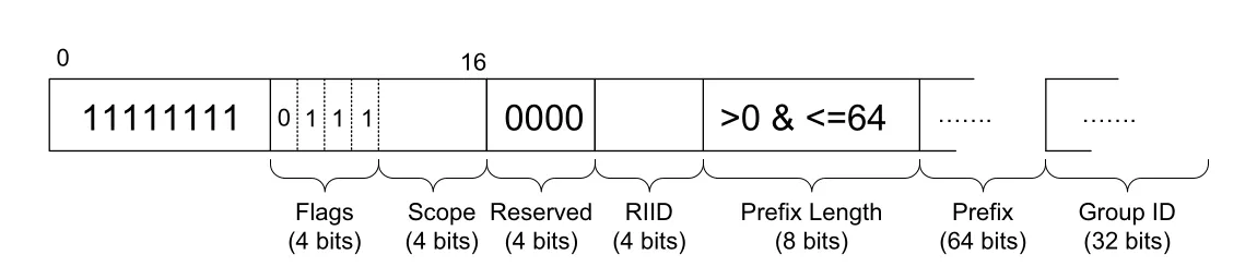
Figure 2-15 · PDF p. 99 · IPv6 multicast address 안에 RP 정보를 embed하는 format
Figure 2-15에서는 RIID field와 prefix length/prefix를 사용해 RP의 unicast IPv6 address를 재구성할 수 있다. 예를 들어 multicast address ff75:940:2001:db8:dead:beef:f00d:face는 site-local scope 5, RIID 9, prefix length 0x40 = 64, prefix 2001:db8:dead:beef를 담으므로 RP address는 2001:db8:dead:beef::9가 된다.
IPv6 reserved multicast address에는 ff02::1 all nodes, ff02::2 all routers, ff02::1:ffxx:xxxx solicited-node address range, ff3x::/32 SSM block처럼 protocol operation에 직접 쓰이는 것들이 많다. 핵심은 IPv6가 broadcast를 없앤 대신, scope가 정교한 multicast address를 기본 control-plane mechanism으로 많이 사용한다는 점이다.
2.5.5 Anycast Addresses
anycast address는 문법상 unicast IPv4/IPv6 address이지만, network 위치에 따라 서로 다른 host를 가리킨다. 여러 location에서 같은 unicast route를 advertise하면, routing system은 sender에게 가장 적절하거나 가까운 instance로 traffic을 보낸다. 그래서 anycast는 “하나의 address, 여러 service instances, routing이 선택한 하나의 destination”이라는 의미를 갖는다.
anycast는 공통 service instance를 찾는 데 유용하다. DNS server, 6to4 gateway, multicast routing의 RP처럼 어느 instance를 쓰든 service semantics가 유지되는 경우에 잘 맞는다. 다만 connection state가 길게 유지되는 application에서는 route change로 instance가 바뀔 때 문제가 될 수 있으므로, service design과 routing stability를 함께 고려해야 한다.
2.6 Allocation
IP address space는 hierarchical authority에 의해 큰 chunk 단위로 allocated된다. 최상위에는 IANA가 있고, IANA는 Internet protocol에서 쓰이는 address와 여러 number resource allocation에 대한 넓은 책임을 갖는다. allocation은 주로 global unicast address space에서 중요하지만, multicast나 special-use address도 특정 경우에는 allocation 대상이 된다.
2.6.1 Unicast
unicast IPv4/IPv6 address space에서 IANA는 allocation authority의 상당 부분을 RIRs(Regional Internet Registries)에 위임한다. RIR들은 NRO(Number Resource Organization)를 통해 서로 조정한다. RIR은 large address block을 country-level registry, large ISP 등에 allocate하고, ISP는 다시 customer에게 prefix를 제공한다.
ISP가 customer에게 제공하는 address는 보통 provider-aggregatable(PA) address다. PA address는 ISP가 가진 더 큰 prefix와 함께 aggregate될 수 있으므로 global routing table을 줄이는 데 유리하다. 대신 non-portable address라고도 불리며, customer가 provider를 바꾸면 address renumbering이 필요할 수 있다.
provider-independent(PI) address는 ISP가 아니라 user/customer에게 직접 allocated되는 address space다. PI address는 provider를 바꿔도 유지할 수 있어 provider lock을 줄인다. 하지만 ISP의 own prefix와 numerically adjacent하지 않을 가능성이 크므로 aggregation이 어렵다. 즉 PI는 customer의 운영 독립성에는 좋지만, ISP와 global routing system에는 더 많은 routing table entry라는 비용을 만든다. ISP가 PI route를 받아 주는 데 추가 비용을 요구하거나 거절할 수 있는 이유가 여기에 있다.
WHOIS 또는 RIR database query는 address allocation이 어떤 상위 block에서 내려왔는지 확인하는 데 쓰인다. 예를 들어 어떤 IPv4 address가 72.1.140.192/27 block에 있고, 그 block이 다시 72.1.128.0/18 PA block의 일부라면, address ownership과 aggregation hierarchy를 함께 볼 수 있다. RIPE database에서 ASSIGNED PI 같은 status가 보이면 provider-independent block임을 뜻한다.
RPSL(Routing Policy Specification Language)은 ISP가 routing policy를 표현하는 데 쓰이는 database record format이다. 이런 registry/policy 정보는 단순 주소 조회를 넘어, operator가 routing instability를 줄이도록 router configuration을 구성하는 데 도움을 준다.
2.6.2 Multicast
multicast address allocation은 unicast보다 더 복잡하다. multicast group address는 scope, 결정 방식(static, dynamic agreement, algorithmic), ASM/SSM 여부에 따라 의미가 달라진다. non-global scope의 multicast address는 여러 Internet location에서 재사용될 수 있고, network administrator가 administrative scope block에서 구성하거나 host가 자동 선택할 수 있다.
globally scoped static multicast address는 모든 Internet site에 적용될 만한 제한된 용도에 쓰여야 한다. address space가 특히 IPv4에서는 제한적이기 때문이다. algorithmically determined multicast address는 GLOP처럼 AS number를 기반으로 하거나, UBM/IPv6 unicast-prefix-based multicast처럼 관련 unicast prefix allocation을 기반으로 만들 수 있다. SSM은 global SSM block, administrative scope, 또는 prefix가 zero인 IPv6 unicast-prefix-based address 등 여러 형태와 결합될 수 있다.
실무적으로 multicast address management는 address format만의 문제가 아니라 multicast routing, provider coordination, application support까지 얽힌다. 일반 사용자는 거의 의식하지 못할 수 있지만, multicast를 쓰는 application 개발자나 network administrator에게는 scope, group allocation, routing boundary를 함께 설계해야 하는 문제다.
2.7 Unicast Address Assignment
site가 unicast IP address range를 allocated받으면 network administrator는 그 range를 각 network interface에 어떻게 assign할지, subnet structure를 어떻게 만들지 결정해야 한다. single physical network segment만 있는 home network라면 단순하지만, 여러 LAN, firewall/NAT, DMZ, multiple ISP가 있는 enterprise에서는 address plan이 routing, security, service exposure와 함께 설계되어야 한다.
2.7.1 Single Provider/No Network/Single Address
가장 단순한 Internet service는 ISP가 single computer에 single IP address를 주는 구조다. DSL 같은 point-to-point link에서는 address가 temporary일 수 있고, user computer가 Internet으로 보내는 traffic은 그 address를 source IPv4 address로 가진다. 하지만 이 단순한 host도 loopback 127.0.0.1, IPv4 All Hosts multicast 224.0.0.1, IPv6 loopback ::1, IPv6 All Nodes multicast ff02::1, interface별 link-local address 등 여러 active address/group을 동시에 가질 수 있다.
Linux ifconfig/netstat -gn 예시는 point-to-point interface ppp0에 IPv4 address가 붙고, host가 IPv4/IPv6 multicast group membership을 갖는 모습을 보여준다. mDNS(multicast DNS)는 static IPv4 multicast address 224.0.0.251을 사용한다. 핵심은 “single address service”라고 해도 OS 내부에는 loopback, multicast, link-local 같은 여러 address context가 함께 존재한다는 점이다.
2.7.2 Single Provider/Single Network/Single Address
집에 여러 computer가 있으면 ISP가 준 single public address를 router 또는 router 역할의 computer가 공유한다. home LAN/WLAN 내부 host들은 private address를 쓰고, router는 ISP 쪽으로 packet을 forward하면서 NAT, Windows 용어로 ICS(Internet Connection Sharing)를 수행한다. ISP 관점에서는 여전히 single IP address만 사용하는 customer처럼 보인다.
오늘날 home router는 이 과정을 자동화한다. 내부 host에는 DHCP로 private address와 default gateway, DNS 정보를 주고, ISP-facing link의 address도 필요하면 자동으로 구성한다. DHCP와 host configuration의 자세한 동작은 Chapter 6으로 이어진다.
2.7.3 Single Provider/Multiple Networks/Multiple Addresses
조직이 Internet server를 운영하거나 여러 LAN을 가진 경우 single temporary address로는 부족하다. Web server, login server, mail server처럼 외부에서 접근해야 하는 host는 stable public IP address가 필요하고, internal network와 external service network를 firewall/NAT 경계로 나누어야 한다.
small/medium enterprise에서는 ISP로부터 public routable prefix를 받고, 일부 address는 DMZ(demilitarized zone) server에 직접 assign하며, 나머지는 NAT router의 NAT pool로 사용하기도 한다. DMZ는 primary firewall 바깥 또는 경계 영역에 두어 Internet-visible server를 internal network와 분리하는 설계다.
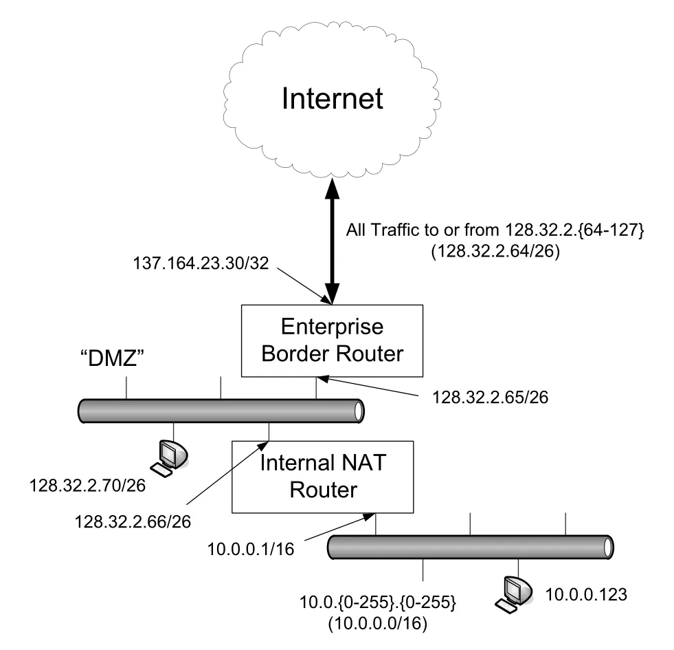
Figure 2-16 · PDF p. 107 · public `/26` prefix, DMZ, internal NAT router를 가진 enterprise address assignment 예
Figure 2-16의 enterprise는 128.32.2.64/26 public prefix를 받았고, DMZ server에는 128.32.2.66/26, 128.32.2.70/26 같은 routable address를 준다. internal NAT router는 바깥쪽에 public address를 갖고, 안쪽에는 10.0.0.0/16 private network를 제공한다. 이 구조의 장점은 두 가지다. 첫째, DMZ server가 compromise되어도 internal hosts를 별도 NAT/firewall boundary 뒤에 둘 수 있다. 둘째, 내부 address plan은 private space를 자유롭게 써도 되므로 public IPv4 address 부족의 압력을 줄인다.
2.7.4 Multiple Providers/Multiple Networks/Multiple Addresses (Multihoming)
multihoming은 조직이 redundancy, availability, policy control 등을 위해 둘 이상의 ISP에 연결하는 방식이다. CIDR 환경에서는 single ISP customer가 보통 그 ISP의 PA address를 쓰므로, 두 번째 ISP를 붙일 때 어떤 address를 host에 사용할지가 문제가 된다.
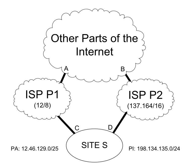
Figure 2-17 · PDF p. 108 · multihomed enterprise에서 PA address와 PI address를 사용할 때의 routing trade-off
Figure 2-17에서 site S가 ISP P1의 PA prefix 12.46.129.0/25를 쓰면, P1은 이 prefix를 자기 큰 block 12/8 안으로 aggregate할 수 있다. 하지만 P2는 이 prefix가 자기 137.164/16 block과 인접하지 않으므로 aggregate할 수 없다. 게다가 다른 Internet host 입장에서는 12.0.0.0/8보다 12.46.129.0/25가 더 specific하므로 longest matching prefix rule에 따라 P2 쪽 route가 선호될 수 있다. 결과적으로 P2는 aggregate하지 못하면서도 S의 traffic을 많이 운반하는 불리한 위치가 된다.
site S가 PI prefix 198.134.135.0/24를 쓰면 P1과 P2가 같은 prefix를 advertise하므로 경로 선택이 더 대칭적이고, provider를 바꿔도 site 내부 address를 renumbering하지 않아도 된다. 하지만 어느 ISP도 이 prefix를 자기 aggregate에 넣을 수 없으므로 global routing table에는 별도 entry가 남는다. 이 때문에 site operator는 PI를 선호하고, ISP와 Internet scalability 관점에서는 PA가 선호된다.
IPv6 multihoming은 단순히 주소가 많아졌다고 해결되는 문제가 아니다. IP address가 identifier와 locator를 동시에 맡기 때문이다. identifier는 “누구와 통신 중인가”를, locator는 “routing system에서 어디에 있는가”를 뜻한다. provider가 바뀌거나 path가 바뀌면 locator는 변할 수 있지만, transport connection은 같은 peer identity를 유지하고 싶어 한다.
Multi6와 Shim6는 IPv6 multihoming에서 identifier/locator split을 다루려는 접근이다. Shim6는 network-layer shim을 두어 transport protocol이 보는 upper-layer protocol identifier와 실제 locator IP address를 분리하고, communicating peers가 network condition에 따라 사용할 locator와 switch 시점을 합의하도록 한다. HIP(Host Identity Protocol)는 cryptographic host identifier, 즉 public/private key pair 기반 identity로 host를 식별하려는 실험적 접근이다.
2.8 Attacks Involving IP Addresses
IP address 자체는 숫자이므로 IP address만으로 완성되는 공격은 많지 않다. 하지만 spoofed datagram, misattribution, privacy 추적, address-based blocking처럼 IP address의 식별자/위치자 성격을 이용하는 문제가 있다.
IP address를 사람 또는 조직의 identity처럼 사용하는 것은 조심해야 한다. 많은 access network에서 IP address는 temporary이고, 시간이 지나면 다른 user에게 reassigned될 수 있다. 따라서 address-to-user database의 timestamp가 조금만 틀려도 잘못된 attribution이 생긴다.
또한 public access point, 의도치 않게 open된 wireless router, compromised host, botnet을 통해 traffic이 나갈 수 있다. 이 경우 IP address가 가리키는 subscriber나 site owner가 실제 originator가 아닐 수 있다. IP address는 routing locator로는 강하지만, legal/forensic identity로는 약한 증거일 수 있다.
2.9 Summary
IP address는 Internet system에서 network interface를 identify하고 locate한다. unicast address는 하나의 interface를 가리키고, IPv4 broadcast, IPv4/IPv6 multicast, IPv4/IPv6 anycast는 하나 이상 또는 위치에 따라 다른 interface를 가리킨다. IPv4 interface는 32-bit address를, IPv6 interface는 보통 여러 128-bit address를 함께 가진다.
unicast address는 hierarchical administrative entities가 block 단위로 allocate한다. ISP가 받은 address block의 subrange를 customer에게 주면 보통 PA(provider-aggregatable) address가 되고, customer가 직접 소유한 address는 PI(provider-independent) address가 된다. PA는 aggregation에 유리하지만 provider 변경 시 renumbering이 필요할 수 있고, PI는 portability에 유리하지만 global routing table size를 키운다.
classful A/B/C network structure는 fixed-size allocation 때문에 address 낭비와 routing scalability 문제를 만들었다. CIDR은 arbitrary prefix length를 허용해 더 다양한 block size를 allocate하게 했고, numerically adjacent prefixes를 aggregation하여 routing table state를 줄이는 길을 열었다. CIDR은 Internet core routing system에 가해진 마지막 수준의 근본적 변화로 볼 수 있다.
IPv6 unicast address는 scope 개념이 더 뚜렷하다. node-local, link-local, global 같은 scope는 address가 유효한 범위를 나타낸다. link-local address는 보통 fe80::/10 prefix와 IID(interface identifier)를 결합해 만들며, IID는 EUI-64 기반 또는 privacy를 위한 randomized value일 수 있다. 이 구조는 IPv6 autoconfiguration과 Chapter 6의 host configuration으로 이어진다.
IPv4는 broadcast와 multicast를 모두 지원하지만, IPv6는 broadcast를 없애고 multicast를 더 정교하게 사용한다. multicast sender는 group address를 destination으로 보내며, receiver set을 직접 알지 못한다. IPv6 multicast format은 Scope, Flags, Group ID, unicast-prefix-based allocation, IID-based link-local multicast, RP embedding 등 다양한 변형을 통해 global coordination과 routing discovery 문제를 완화하려 한다.
NAT의 widespread use는 모든 Internet-attached host가 unique public IPv4 address를 가져야 한다는 압력을 늦추어 IPv6 adoption을 지연시켰다. 그러나 routable IPv4 address는 근본적으로 finite resource이며, long-term solution은 더 큰 address space와 개선된 address architecture를 가진 IPv6 쪽으로 이어진다.
연결 관계
- Chapter 3 Link Layer: IPv6 IID가 MAC/EUI-48/EUI-64와 연결되고, link-local/broadcast/multicast 동작은 link-layer delivery와 맞물린다.
- Chapter 4 ARP: IPv4 address와 link-layer address mapping, local network에서 address resolution을 다룬다.
- Chapter 5 IP: prefix, longest prefix match, forwarding table, aggregation이 실제 forwarding algorithm으로 이어진다.
- Chapter 6 DHCP/Autoconfiguration: IPv4 DHCP, IPv6 autoconfiguration, link-local address, IID 생성이 구체화된다.
- Chapter 7 NAT/Firewall/VPN: private address, NAT pool, DMZ, enterprise boundary 설계가 확장된다.
- Chapter 8 ICMPv6: IPv6 Neighbor Discovery와 multicast/control-plane 주소 사용이 연결된다.
- Chapter 9 Broadcasting and Multicasting: IPv4 broadcast, IPv4/IPv6 multicast group join/leave와 multicast routing이 깊어진다.
- Chapter 18 Security: spoofing, attribution, cryptographic host identifier, HIP, privacy address와 연결된다.
오해하기 쉬운 내용
- IP address는 host 전체보다 interface를 식별하는 개념에 가깝다. multihomed host는 여러 IP address를 가질 수 있다.
- subnet mask와 CIDR mask는 비슷하지만, subnet mask는 site-local 구분에서 출발했고 CIDR prefix는 global routing system에서도 보인다.
/24가 항상 class C라는 뜻은 아니다. CIDR에서는 classful boundary가 제거되었고 prefix length가 명시적 의미를 가진다.255.255.255.255limited broadcast와 subnet directed broadcast는 다르다. directed broadcast forwarding은 보안상 기본 비활성화되어 있다.- IPv6에는 broadcast address가 없다. IPv4 broadcast가 하던 많은 역할은 IPv6 multicast가 맡는다.
- private address는 Internet에서 쓸 수 없는 address가 아니라 public Internet에서 route되지 않는 address다. NAT나 tunnel과 결합해 외부 통신이 가능하다.
- anycast는 별도 address family가 아니라 같은 unicast address를 여러 location에서 advertise하는 routing 기법이다.
- PI address는 site에는 편리하지만 routing scalability에는 비용이 있다.
- IP address만으로 사람을 식별하는 것은 위험하다. temporary reassignment, NAT, public Wi-Fi, botnet 때문에 attribution이 틀릴 수 있다.
면접 질문
- IPv4 dotted-quad notation과 IPv6 colon-hex notation의 차이를 설명하라.
- classful addressing이 왜 address 낭비와 scaling problem을 만들었는가?
- subnet mask를 이용해
128.32.1.14/24의 prefix와 broadcast address를 계산하라. - VLSM이 필요한 이유와 오래된 routing protocol에서 문제가 되는 이유는 무엇인가?
- CIDR이 classful addressing을 어떻게 일반화했고, route aggregation은 어떤 조건에서 가능한가?
- longest prefix match가 multihoming에서 PA/PI route 선택에 어떤 영향을 주는가?
- IPv6 IID는 EUI-48/EUI-64에서 어떻게 만들어지며, privacy 문제가 왜 생기는가?
- IPv4 broadcast와 IPv6 multicast의 설계 차이를 설명하라.
- ASM과 SSM의 차이를 multicast receiver의 join 정보 관점에서 설명하라.
- PA address와 PI address의 trade-off를 site operator와 ISP 관점에서 비교하라.
- anycast address가 DNS 같은 service에 적합한 이유와 주의점을 설명하라.
- IP address 기반 attribution이 왜 부정확할 수 있는가?