개요
Transport layer는 application layer와 network layer 사이에 있으며, 서로 다른 hosts에서 실행되는 application processes에게 직접적인 communication service를 제공한다. Chapter 2에서는 application이 TCP/UDP sockets를 어떻게 쓰는지 보았다면, Chapter 3는 TCP/UDP가 그 services를 어떻게 제공하는지로 내려간다.
이 장의 핵심 축은 네 가지다. 첫째, host-to-host delivery를 process-to-process delivery로 확장하는 multiplexing/demultiplexing. 둘째, unreliable channel 위에서 reliable data transfer를 만드는 원리. 셋째, TCP가 connection, segment, RTT estimation, reliable transfer, flow control, connection management를 구현하는 방식. 넷째, network congestion을 왜 제어해야 하며 TCP congestion control이 어떤 규칙으로 sending rate를 조절하는지다.
핵심 개념
3.1 Introduction and Transport-Layer Services
logical communication: process 사이의 통신처럼 보이게 하기
transport-layer protocol은 서로 다른 hosts에서 실행되는 application processes 사이에 logical communication을 제공한다. application 입장에서는 두 processes가 직접 연결된 것처럼 messages를 주고받지만, 실제로는 여러 routers, links, ISPs, access networks를 통과한다.
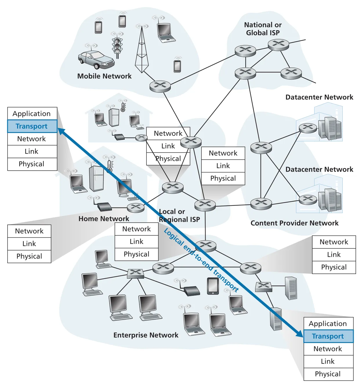 Figure 3.1 · PDF p. 194 · transport layer가 physical path가 아니라 end-system application processes 사이의 logical communication을 제공하는 위치
transport layer는 end systems에만 구현되고 routers에는 구현되지 않는다. sender side에서는 application-layer message를 필요하면 작은 chunks로 나누고 transport-layer header를 붙여 transport-layer segment를 만든다. 이 segment는 network layer로 내려가 IP datagram 안에 encapsulation된다. routers는 datagram의 network-layer fields를 보고 forwarding할 뿐, 내부의 transport-layer header를 해석하지 않는다. receiver side에서는 network layer가 datagram에서 segment를 꺼내 transport layer로 올리고, transport layer가 segment를 처리해 data를 receiving application process가 읽을 수 있게 한다.
이 구조는 Chapter 1의 layered architecture와 Chapter 2의 socket model을 연결한다. application developer는 socket 위의 logic을 작성하고, transport protocol은 socket 아래에서 process-to-process delivery abstraction을 제공한다.
transport layer와 network layer의 차이
network layer는 hosts 사이의 logical communication을 제공한다. transport layer는 그 위에서 processes 사이의 logical communication을 제공한다. 책의 비유로 보면, postal service가 house-to-house delivery를 제공하고, 집 안의 Ann/Bill이 각 아이에게 편지를 나눠 주는 household-internal delivery를 제공한다. 여기서 houses는 hosts, cousins는 processes, postal service는 network-layer protocol, Ann/Bill은 transport-layer protocol에 해당한다.
이 차이는 subtle하지만 중요하다.
| Layer | 제공하는 logical communication | packet 처리 위치 | 예 |
|---|---|---|---|
| network layer | host-to-host | end systems + routers | IP datagram forwarding |
| transport layer | process-to-process | end systems only | TCP/UDP segment handling |
transport service는 underlying network-layer service model에 의해 제약을 받는다. IP가 delay bound나 bandwidth guarantee를 제공하지 않으면 TCP/UDP도 application에게 그런 guarantee를 직접 제공할 수 없다. 하지만 어떤 service는 network layer가 제공하지 않아도 transport layer가 end systems에서 구현할 수 있다. 대표적으로 TCP는 unreliable IP 위에서 reliable data transfer를 제공하고, 보안 chapter에서 볼 TLS는 TCP 위에서 confidentiality와 authentication을 제공한다.
Internet transport overview: UDP와 TCP
Internet application은 transport protocol로 주로 UDP(User Datagram Protocol) 또는 TCP(Transmission Control Protocol)를 선택한다. 책은 TCP packet과 UDP packet을 모두 transport-layer segment라고 부르되, RFC 문헌에서는 UDP packet을 UDP datagram이라고도 부른다는 용어 차이를 짚는다. network-layer packet은 IP datagram으로 구분해서 기억하면 좋다.
IP(Internet Protocol)는 best-effort delivery service다. IP는 segment delivery, in-order delivery, data integrity를 보장하지 않는다. 그래서 IP는 unreliable service라고 부른다. transport layer의 가장 기본 책임은 이 host-to-host best-effort service를 process-to-process service로 확장하는 것이다.
| Protocol | 기본 service | Chapter 3에서 볼 핵심 |
|---|---|---|
| UDP | unreliable, connectionless | multiplexing/demultiplexing, checksum |
| TCP | reliable, connection-oriented | reliable data transfer, flow control, congestion control, connection management |
UDP가 제공하는 것은 최소 기능이다. process-to-process delivery를 위한 multiplexing/demultiplexing과 segment header의 error-detection field를 통한 integrity checking이 전부에 가깝다. TCP는 여기에 reliable data transfer를 더한다. flow control, sequence numbers, acknowledgments, timers를 이용해 sending process의 byte stream이 receiving process에 correct order로 도착하도록 만든다. TCP congestion control은 application 하나를 위한 service라기보다 Internet 전체를 위한 service다. 한 TCP connection이 congested links와 routers를 과도하게 점유하지 않도록 sending rate를 조절한다.
3.2 Multiplexing and Demultiplexing
host-to-host delivery를 socket delivery로 바꾸는 기능
transport layer는 network layer에서 올라온 segment를 process에 직접 주지 않고 socket에 전달한다. receiving host에는 동시에 여러 sockets가 있을 수 있으므로, transport layer는 segment header fields를 보고 어느 socket으로 보낼지 결정해야 한다. 이 작업이 demultiplexing이다.
반대로 sender side에서는 여러 sockets에서 나온 application data chunks를 모으고, 나중에 receiver가 demultiplexing할 수 있도록 header information을 붙여 segments를 만든다. 이 작업이 multiplexing이다.
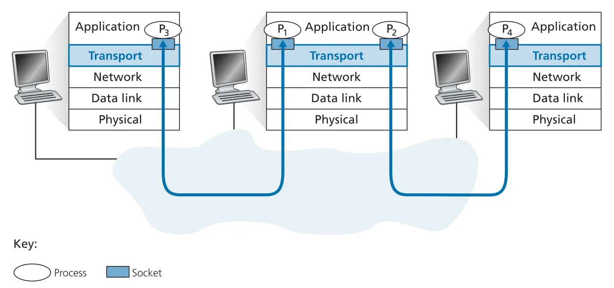 Figure 3.2 · PDF p. 199 · transport layer가 여러 sockets에서 나온 data를 multiplexing하고, 도착 segments를 올바른 socket으로 demultiplexing하는 구조
transport-layer multiplexing/demultiplexing이 가능하려면 두 조건이 필요하다. 첫째, sockets가 unique identifier를 가져야 한다. 둘째, 각 segment가 receiver socket을 식별하는 header fields를 가져야 한다. Internet transport에서는 source port number와 destination port number가 이 역할의 중심이다.
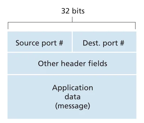 Figure 3.3 · PDF p. 200 · transport-layer segment header의 source port number와 destination port number fields
port number는 16-bit 값이므로 범위는 0부터 65535까지다. 0부터 1023까지는 well-known port numbers로, HTTP 80, FTP 21, SMTP 25, DNS 53처럼 잘 알려진 protocols에 예약된다. 새 application을 만들 때는 well-known port와 충돌하지 않는 port를 골라야 한다.
UDP connectionless multiplexing/demultiplexing
UDP socket은 destination IP address와 destination port number의 2-tuple로 식별된다. receiving host의 UDP demultiplexing은 incoming segment의 destination port number를 보고 해당 socket으로 data를 보낸다. 따라서 source IP address나 source port number가 달라도 destination IP address와 destination port number가 같으면 같은 UDP socket으로 전달된다.
UDP client는 보통 socket 생성 시 OS가 ephemeral port를 자동 배정하게 둔다.
clientSocket = socket(AF_INET, SOCK_DGRAM)반면 server side는 clients가 찾아올 수 있어야 하므로 bind()로 특정 port를 socket에 연결한다.
clientSocket.bind(('', 19157))source port number는 return address의 일부다. A가 B로 UDP segment를 보낼 때 A의 source port가 19157, B의 destination port가 46428이면, B가 reply할 때 destination port는 19157이 된다. 완전한 return address는 source IP address와 source port number의 조합이다.
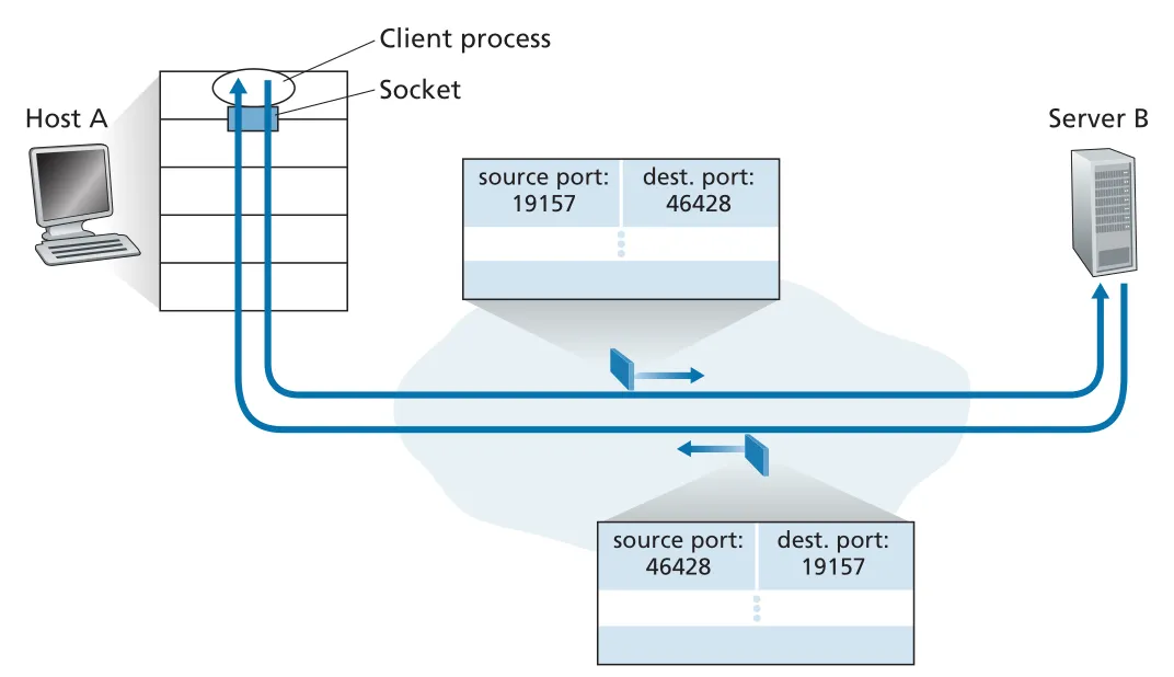 Figure 3.4 · PDF p. 202 · UDP request와 reply에서 source/destination port numbers가 뒤바뀌는 방식
TCP connection-oriented multiplexing/demultiplexing
TCP socket은 UDP보다 더 구체적으로 식별된다. TCP connection socket은 다음 4-tuple로 식별된다.
(source IP address, source port number, destination IP address, destination port number)TCP segment가 host에 도착하면 transport layer는 네 값을 모두 사용해 올바른 connection socket으로 demultiplexing한다. 그래서 서로 다른 clients가 같은 Web server port 80으로 접속하더라도, source IP address와 source port number가 다르면 서로 다른 TCP connection sockets로 구분된다.
TCP server에는 두 종류의 socket이 등장한다. welcoming socket은 특정 server port에서 connection-establishment requests를 기다린다. client가 connect()로 접속하면 server는 accept()를 통해 client별 connectionSocket을 만든다. 이후 같은 4-tuple과 matching되는 segments는 이 connection socket으로 전달된다.
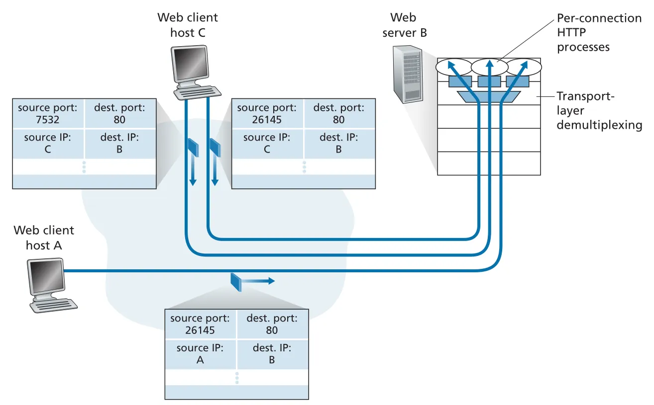 Figure 3.5 · PDF p. 204 · 같은 destination port 80을 쓰더라도 TCP 4-tuple로 여러 HTTP connections를 구분하는 방식
Web server는 port 80에서 들어오는 모든 initial connection-establishment segments와 HTTP request-carrying segments를 받는다. busy Web server에서는 connection마다 process를 만들 수도 있고, 하나의 process 안에서 connection마다 thread와 connection socket을 만들 수도 있다. persistent HTTP에서는 같은 TCP connection/socket으로 여러 HTTP messages를 교환하지만, non-persistent HTTP에서는 request/response마다 새 TCP connection과 socket이 만들어지고 닫히므로 busy server의 성능에 부담이 될 수 있다.
port scanning이 가능한 이유
server process는 open port에서 remote client의 접속을 기다린다. 따라서 어떤 host에서 open ports를 찾으면 그 host에서 어떤 network applications가 실행 중인지 추정할 수 있다. nmap 같은 port scanner는 TCP에서는 connection을 받아들이는 ports를, UDP에서는 UDP segments에 응답하는 ports를 순차적으로 조사한다. system administrator에게는 inventory/security 점검 도구지만, attacker에게는 취약 application을 찾는 reconnaissance 도구가 될 수 있다.
3.3 Connectionless Transport: UDP
UDP는 transport protocol이 할 수 있는 일을 거의 최소한만 수행한다. 완전히 빈 transport protocol이라면 application message를 그대로 network layer에 넘기면 되겠지만, 적어도 process-to-process delivery를 위해 multiplexing/demultiplexing은 필요하다. UDP는 여기에 가벼운 error checking을 더한 정도다.
UDP sender는 application process에서 받은 message에 source port number와 destination port number, length, checksum fields를 붙여 UDP segment를 만들고 IP로 넘긴다. IP는 이 segment를 datagram에 넣어 best-effort로 destination host에 전달한다. destination host에 segment가 도착하면 UDP는 destination port number를 보고 올바른 process/socket에 data를 넘긴다.
UDP가 connectionless인 이유
UDP에서는 sender와 receiver transport entities 사이에 segment를 보내기 전 handshaking이 없다. 그래서 connectionless라고 부른다. DNS가 전형적 예다. DNS client는 DNS query message를 만들고 UDP에 넘기며, UDP는 connection setup 없이 segment를 보내고, reply가 오지 않으면 DNS application이 재전송하거나 다른 name server를 시도하거나 실패를 보고한다.
UDP를 선택하는 이유는 TCP보다 “항상 좋다”가 아니라 “application requirements가 다르다”다.
| UDP 선택 이유 | 설명 |
|---|---|
| finer application-level control | application이 언제 어떤 data를 보낼지 직접 통제한다. TCP congestion control이나 reliable retransmission 때문에 지연되는 것을 피할 수 있다. |
| no connection establishment | three-way handshake delay가 없다. DNS처럼 짧은 query/response에 유리하다. |
| no connection state | send/receive buffers, sequence/ACK state, congestion-control parameters를 유지하지 않는다. 많은 clients를 상대하는 server에 가볍다. |
| small header overhead | UDP header는 8 bytes이고, TCP header는 최소 20 bytes다. |
하지만 UDP의 lack of congestion control은 위험하다. 많은 high-bit-rate UDP senders가 adaptive congestion control 없이 traffic을 밀어 넣으면 routers에서 packet overflow가 늘고, TCP senders는 loss를 congestion signal로 보고 rate를 줄인다. 결과적으로 UDP traffic이 TCP sessions를 crowd out할 수 있다. 따라서 UDP를 쓰는 real-time/multimedia application도 application-level rate adaptation이나 congestion control을 조심스럽게 설계해야 한다.
UDP 위에서 reliability를 직접 만들 수 있는가
가능하다. UDP를 사용하더라도 application이 acknowledgments, retransmissions, timers 같은 mechanisms를 직접 구현하면 reliable data transfer를 만들 수 있다. QUIC은 UDP 위에서 reliability와 congestion control 등을 application-layer protocol로 구현한 대표 사례다. 다만 이는 nontrivial한 작업이다. UDP를 택하면 TCP의 built-in reliability와 congestion control에서 벗어나는 대신, 그 복잡성을 application이 떠안을 수 있다.
UDP segment structure
UDP segment는 header 8 bytes와 application data로 구성된다. header는 네 fields를 가지며 각 field는 2 bytes다.
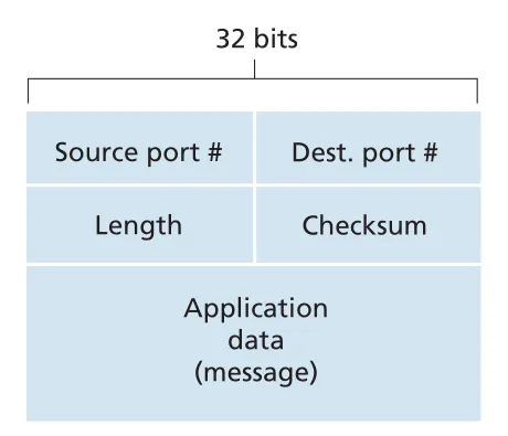 Figure 3.7 · PDF p. 209 · source/destination port, length, checksum으로 이루어진 UDP segment header
| UDP field | 크기 | 역할 |
|---|---|---|
source port # | 2 bytes | reply를 위한 return port, demultiplexing 보조 |
destination port # | 2 bytes | destination host에서 올바른 socket/process 선택 |
length | 2 bytes | UDP header + data 전체 길이, bytes |
checksum | 2 bytes | segment bit errors detection |
length field가 필요한 이유는 UDP data field size가 segment마다 달라질 수 있기 때문이다. checksum은 receiver가 segment 안의 bits가 source-to-destination path에서 바뀌었는지 확인하게 한다.
UDP checksum: 1s complement sum
UDP checksum은 error detection mechanism이다. sender는 segment의 16-bit words를 모두 더하고, overflow는 wrap around한 뒤, 그 sum의 1s complement를 checksum field에 넣는다. receiver는 data words와 checksum을 모두 더한다. error가 없다면 결과는 모든 bits가 1인 값이 된다.
sender:
  checksum = 1s_complement(sum(all 16-bit words, with wraparound))

receiver:
  if sum(all 16-bit words + checksum) == 1111111111111111:
      no detected error
  else:
      detected error
UDP가 checksum을 제공하는 이유는 link layer가 항상 충분한 error detection을 제공한다고 보장할 수 없기 때문이다. 어떤 path의 일부 link-layer protocol은 error checking이 없을 수 있고, router memory에 저장되는 동안 bit error가 생길 수도 있다. 그래서 end-to-end data transfer service가 error detection을 제공하려면 transport layer에서 end-end basis로 확인해야 한다. 이는 end-end principle의 예다.
UDP checksum은 error를 발견할 뿐 recovery는 하지 않는다. 구현에 따라 damaged segment를 discard하거나, warning과 함께 application에 넘길 수 있다. error recovery, ordering, reliability가 필요하다면 application이 UDP 위에 직접 만들거나 TCP 같은 더 복잡한 transport protocol을 선택해야 한다.
3.4 Principles of Reliable Data Transfer
reliable data transfer는 transport layer뿐 아니라 link layer, application layer에서도 반복해서 나타나는 네트워킹의 핵심 문제다. 목표는 unreliable channel 위에서 upper layer에게 reliable channel abstraction을 제공하는 것이다. reliable channel에서는 transferred data bits가 corrupted되지 않고, lost되지 않고, sent order 그대로 delivered된다. TCP가 Internet applications에게 제공하는 reliable byte-stream service가 이 모델의 대표 구현이다.
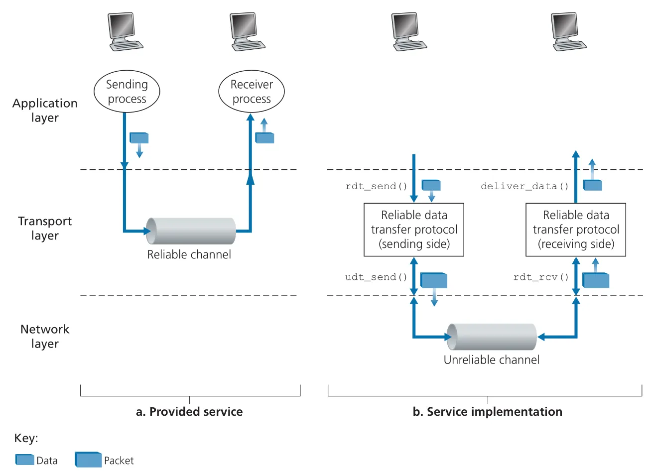 Figure 3.8 · PDF p. 212 · upper layer에는 reliable channel처럼 보이지만, 실제 구현은 unreliable channel 위의 sender/receiver protocol이 맡는 구조
이 절의 추상 interface는 다음처럼 기억하면 된다.
| Interface | 호출 주체 | 의미 |
|---|---|---|
rdt_send(data) | sender upper layer | reliable transfer protocol에 data 전송 요청 |
udt_send(packet) | rdt sender/receiver | unreliable lower channel로 packet 전송 |
rdt_rcv(packet) | lower channel | receiver side rdt에 packet 도착 알림 |
deliver_data(data) | rdt receiver | upper layer에 data 전달 |
이 절은 설명을 단순하게 하기 위해 unidirectional data transfer를 다룬다. 하지만 control packets인 ACK/NAK는 reverse direction으로도 오가므로, 실제 protocol은 data packets와 control packets를 모두 고려해야 한다. 또한 여기서는 channel이 packet reordering은 하지 않고, corruption/loss만 일으킬 수 있다고 가정한다.
rdt1.0: perfectly reliable channel
rdt1.0은 underlying channel이 완전히 reliable할 때의 trivial protocol이다. sender는 rdt_send(data)가 오면 make_pkt(data)로 packet을 만들고 udt_send(packet)으로 보낸다. receiver는 rdt_rcv(packet)이 오면 data를 추출해 deliver_data(data)를 호출한다.
이 경우에는 feedback이 필요 없다. packet corruption도 loss도 없고, receiver가 sender 속도를 따라갈 수 있다고 가정하기 때문이다. 즉 rdt1.0은 reliable transfer 문제가 어려워지는 지점이 “channel이 무엇을 잘못할 수 있는가”에 달려 있음을 보여주는 출발점이다.
rdt2.0: bit errors와 ARQ
더 현실적인 channel은 packet bits를 corrupt할 수 있다. 이때 reliable data transfer는 ARQ(Automatic Repeat reQuest) 형태가 된다. ARQ protocol에는 세 가지 능력이 필요하다.
| ARQ capability | 역할 |
|---|---|
error detection | checksum 같은 extra bits로 packet corruption 감지 |
receiver feedback | receiver가 ACK/NAK로 정상 수신 여부를 sender에게 알림 |
retransmission | corrupted packet을 sender가 다시 보냄 |
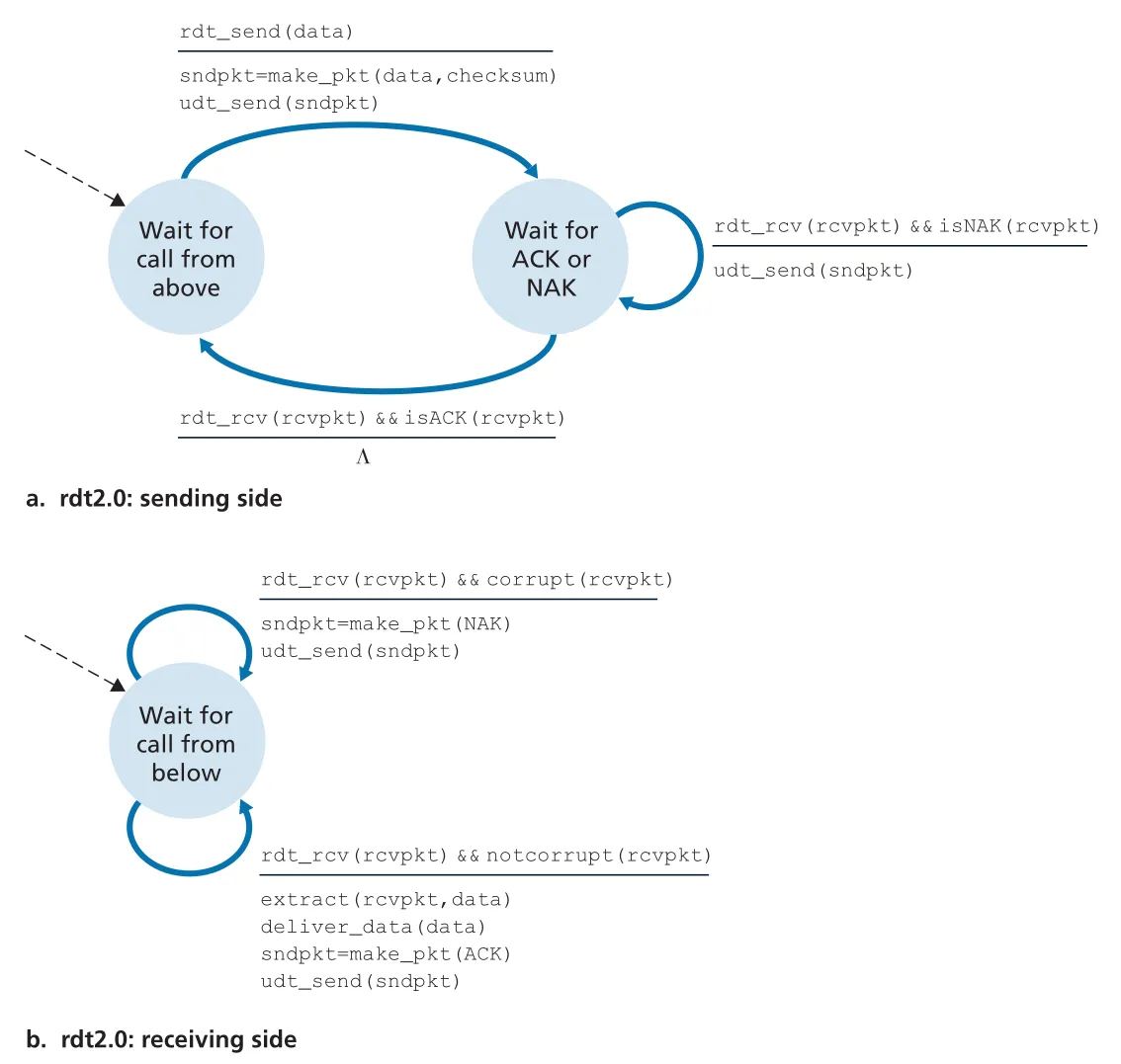 Figure 3.10 · PDF p. 216 · bit error가 있는 channel에서 ACK/NAK와 retransmission을 사용하는 rdt2.0 sender/receiver FSM
rdt2.0 sender는 data packet을 보낸 뒤 ACK 또는 NAK를 기다린다. ACK가 오면 다음 data를 받을 수 있고, NAK가 오면 마지막 packet을 retransmit한다. 이 구조는 stop-and-wait protocol이다. sender는 현재 packet이 receiver에게 올바르게 도착했다는 확신을 얻기 전까지 upper layer에서 새 data를 받아 보내지 않는다.
rdt2.0의 fatal flaw는 ACK/NAK 자체가 corrupted될 수 있다는 점이다. sender가 garbled ACK/NAK를 받으면 receiver가 마지막 data packet을 제대로 받았는지 알 수 없다. 그냥 retransmit하면 duplicate packet이 생길 수 있고, receiver는 이 duplicate가 새 data인지 retransmission인지 구분해야 한다.
sequence number: duplicate packet 구분
duplicate 문제의 표준 해결책은 data packet에 sequence number field를 넣는 것이다. stop-and-wait에서는 1-bit sequence number만 있어도 충분하다. sender는 sequence number 0과 1을 번갈아 사용하고, receiver는 같은 sequence number가 다시 오면 retransmission으로 판단할 수 있다. 이 아이디어는 TCP의 byte sequence numbers로 이어진다.
rdt2.x 계열의 발전은 다음처럼 정리된다.
| Protocol | channel model | 추가 mechanism | 핵심 한계/변화 |
|---|---|---|---|
rdt2.0 | data packet bit errors | checksum, ACK, NAK, retransmission | ACK/NAK corruption을 처리하지 못함 |
rdt2.1 | data와 ACK/NAK corruption | sequence number 0/1, ACK/NAK checksum | sender/receiver state가 seq 0/1 기준으로 두 배가 됨 |
rdt2.2 | NAK 없는 bit-error channel | ACK에 acknowledged sequence number 포함, duplicate ACK 활용 | NAK 대신 마지막 correctly received packet에 대한 ACK를 반복 |
rdt2.2의 포인트는 NAK 없이도 NAK와 같은 효과를 낼 수 있다는 것이다. receiver가 corrupted packet을 받거나 expected sequence number가 아닌 packet을 받으면, 마지막으로 올바르게 받은 packet에 대한 ACK를 다시 보낸다. sender가 같은 ACK를 두 번 받으면 duplicate ACK를 통해 다음 packet이 제대로 수신되지 않았음을 추론한다.
rdt3.0: lossy channel과 timer
이제 underlying channel이 packet corruption뿐 아니라 packet loss도 일으킨다고 하자. sender는 data packet이나 ACK가 lost되면 아무 feedback도 받지 못한다. 따라서 sender가 loss를 감지하고 recovery하려면 timer가 필요하다.
sender는 packet을 보낼 때 countdown timer를 시작한다. timeout 전에 올바른 ACK가 오면 timer를 멈추고 다음 sequence number로 넘어간다. timeout이 발생하면 sender는 마지막 packet을 retransmit하고 timer를 다시 시작한다. timeout은 “정말 lost됐다”는 완전한 증거가 아니라 “lost됐을 가능성이 충분히 크다”는 판단이다. 그래서 long delay 때문에 duplicate retransmission이 생길 수 있지만, sequence number가 duplicate delivery를 막는다.
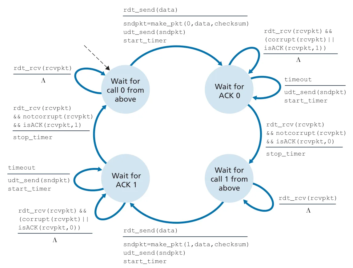 Figure 3.15 · PDF p. 222 · lossy channel에서 timer와 retransmission을 추가한 rdt3.0 sender FSM
rdt3.0은 sequence numbers가 0과 1 사이를 번갈아 움직이므로 alternating-bit protocol이라고도 한다. 핵심 동작은 다음과 같다.
send packet with seq 0
start timer
if ACK 0 arrives before timeout:
stop timer
send next packet with seq 1
else if timeout:
retransmit packet with seq 0
restart timer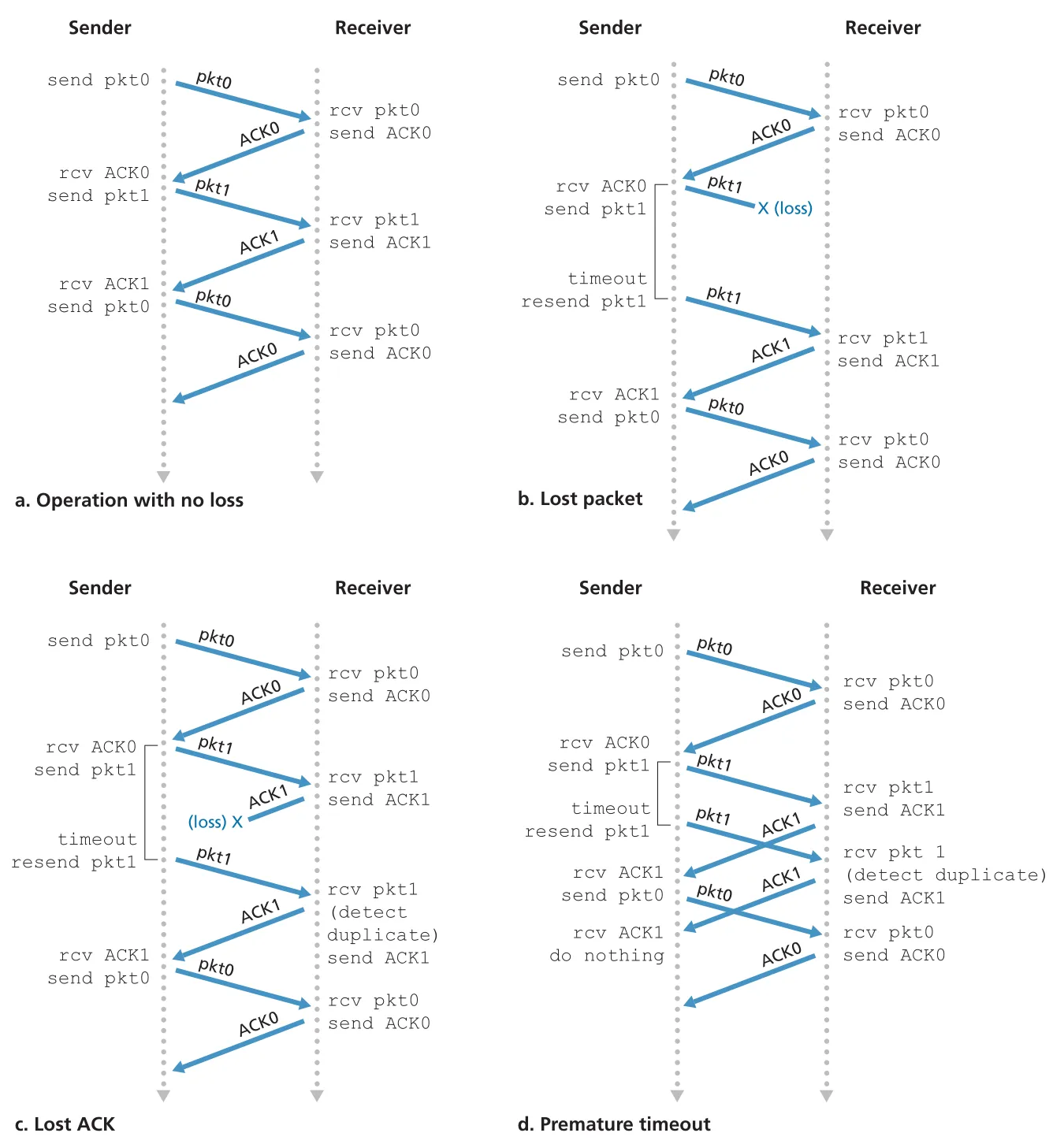 Figure 3.16 · PDF p. 223 · no loss, lost data packet, lost ACK, premature timeout 상황에서 rdt3.0이 동작하는 방식
이 지점까지 reliable data transfer의 핵심 부품이 모두 등장한다.
| Mechanism | 해결하는 문제 |
|---|---|
checksum | bit corruption detection |
ACK/NAK 또는 duplicate ACK | receiver feedback |
sequence number | duplicate packet detection, ordering |
timer | packet/ACK loss detection |
retransmission | loss/corruption recovery |
다음 구간의 pipelining, Go-Back-N, Selective Repeat은 이 부품들을 유지하면서 stop-and-wait의 낮은 utilization 문제를 해결하려는 확장이다.
pipelining: stop-and-wait의 utilization 한계
rdt3.0은 correct하지만 performance가 좋지 않다. 이유는 stop-and-wait이기 때문이다. sender는 packet 하나를 보내고 ACK를 받을 때까지 기다린다. high-speed link와 long RTT가 결합되면 실제 link capacity를 거의 사용하지 못한다.
책의 예시는 , , 인 경우다.
sender는 시간의 약 0.027%만 실제로 bits를 link에 밀어 넣는다. 1 Gbps link를 샀는데 effective throughput은 약 267 kbps에 그치는 식이다. 이는 hardware capacity가 커도 protocol design이 utilization을 제한할 수 있음을 보여 준다.
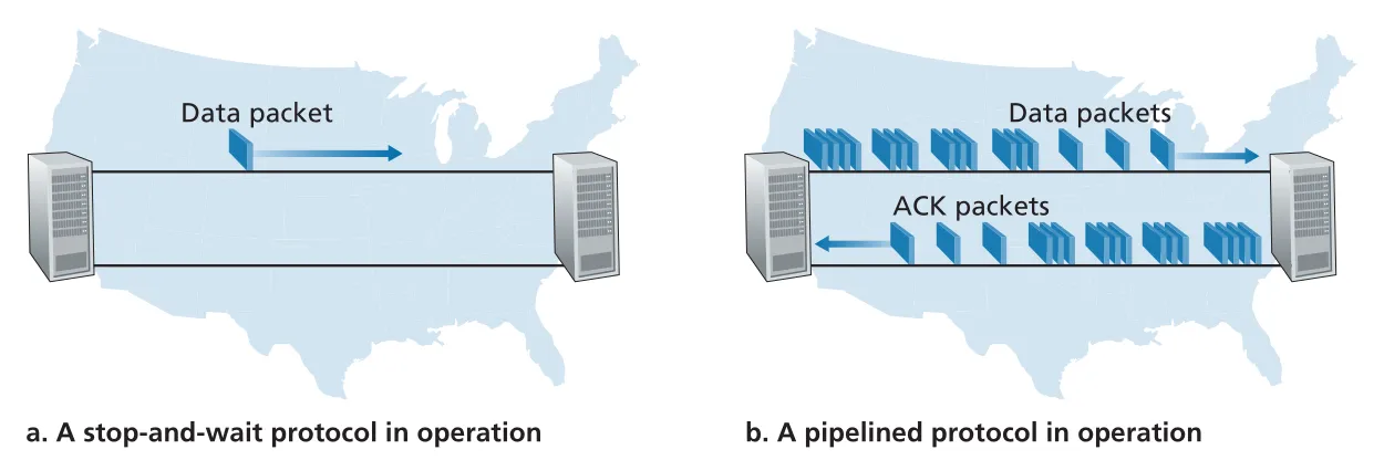 Figure 3.17 · PDF p. 224 · stop-and-wait은 ACK를 기다리지만 pipelined protocol은 여러 packets를 in flight로 유지한다
pipelining은 ACK를 기다리기 전에 여러 packets를 연속으로 보내 pipeline을 채우는 방식이다. pipelining을 쓰면 reliable data transfer protocol에 세 가지 변화가 필요하다.
| 변화 | 이유 |
|---|---|
| larger sequence-number space | 동시에 in-flight인 packets가 각각 unique sequence number를 가져야 함 |
| buffering | sender는 sent but unacknowledged packets를 보관해야 하고, receiver도 out-of-order packets를 buffer할 수 있음 |
| error recovery policy | lost/corrupted/delayed packet에 대해 Go-Back-N 또는 Selective Repeat 같은 전략 필요 |
Go-Back-N (GBN): cumulative ACK와 receiver 단순화
Go-Back-N(GBN)에서 sender는 ACK를 기다리지 않고 여러 packets를 보낼 수 있지만, outstanding unacknowledged packets 수가 window size 을 넘지 못한다. sender는 base와 nextseqnum으로 window 상태를 관리한다.
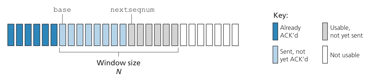 Figure 3.19 · PDF p. 227 · GBN sender가 sequence number space에서 ACKed, sent-not-ACKed, usable, not-usable 영역을 보는 방식
GBN sender sequence number space는 네 구간으로 나뉜다.
| 구간 | 의미 |
|---|---|
[0, base-1] | already transmitted and acknowledged |
[base, nextseqnum-1] | sent but not yet acknowledged |
| window 안에 있어 즉시 보낼 수 있음 | |
| window 밖이라 아직 보낼 수 없음 |
GBN은 sliding-window protocol이다. ACK가 오면 window가 앞으로 slide한다. sequence number field가 bits라면 sequence number space는 이고, 연산은 modulo 로 이루어진다. TCP도 32-bit sequence number field를 쓰지만, TCP sequence number는 packets가 아니라 byte stream의 bytes를 센다.
GBN sender는 세 events에 반응한다.
| Event | sender action |
|---|---|
rdt_send(data) | window가 full이 아니면 packetize/send, full이면 buffer하거나 upper layer에 나중에 재시도하게 함 |
ACK n received | cumulative ACK로 해석하고 로 이동 |
timeout | oldest unacknowledged packet부터 nextseqnum-1까지 모두 retransmit |
GBN receiver는 매우 단순하다. expected sequence number를 가진 in-order packet이 오면 data를 upper layer에 deliver하고 ACK를 보낸다. out-of-order packet은 correctly received라도 discard하고, 가장 최근 in-order packet에 대한 ACK를 다시 보낸다. receiver buffering이 단순해지는 대신, sender가 timeout 때 이미 받았던 packets까지 다시 보낼 수 있다.
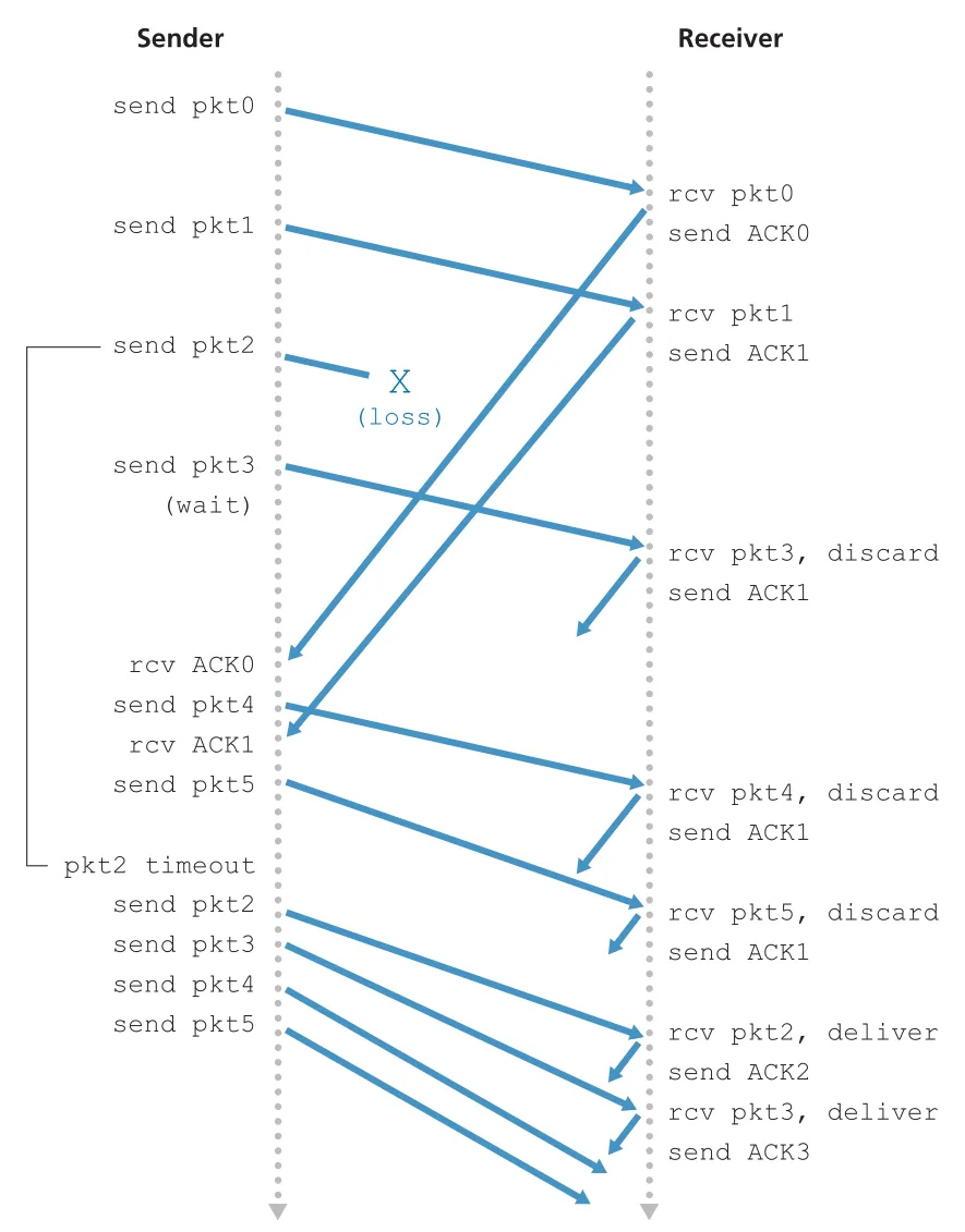 Figure 3.22 · PDF p. 231 · packet 2 loss 뒤 GBN receiver가 out-of-order packets 3, 4, 5를 discard하고 sender가 window 뒤쪽 packets까지 재전송하는 흐름
GBN은 sequence numbers, cumulative acknowledgments, checksums, timeout/retransmit을 모두 사용한다. 이들은 이후 TCP reliable transfer에서 다시 등장한다. 그러나 window size와 bandwidth-delay product가 크고 error probability가 높으면, 단일 packet error가 많은 unnecessary retransmissions를 일으킨다.
Selective Repeat (SR): 필요한 packet만 재전송
Selective Repeat(SR)은 GBN의 낭비를 줄이기 위해 receiver가 correctly received packets를 개별적으로 ACK하고, sender는 lost/corrupted로 의심되는 packets만 retransmit한다. 이 때문에 receiver는 out-of-order packets를 discard하지 않고 buffer한다.
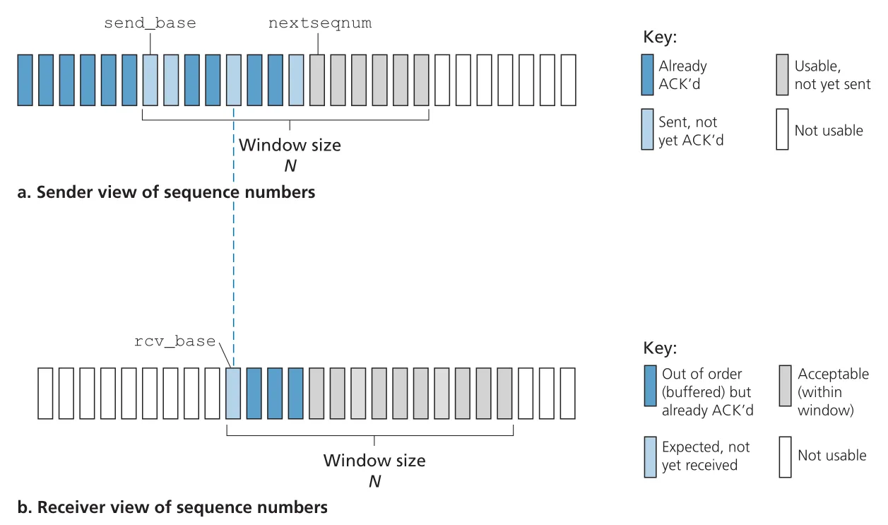 Figure 3.23 · PDF p. 232 · SR에서 sender window와 receiver window가 서로 다를 수 있으며, receiver는 out-of-order buffered packets를 관리한다
SR sender와 receiver 동작은 다음처럼 대비된다.
| 구분 | SR sender | SR receiver |
|---|---|---|
| window | unacknowledged packets 제한 | acceptable sequence numbers 제한 |
| ACK 처리 | packet별 ACK를 받으면 해당 packet을 received로 mark | correctly received packet은 in-order 여부와 무관하게 ACK |
| timeout | packet별 logical timer로 해당 packet만 retransmit | timeout 처리 없음 |
| buffering | sent but unacknowledged packets 보관 | out-of-order packets buffer |
| delivery | sender는 delivery 없음 | missing lower seq packets가 도착하면 buffered consecutive packets를 batch deliver |
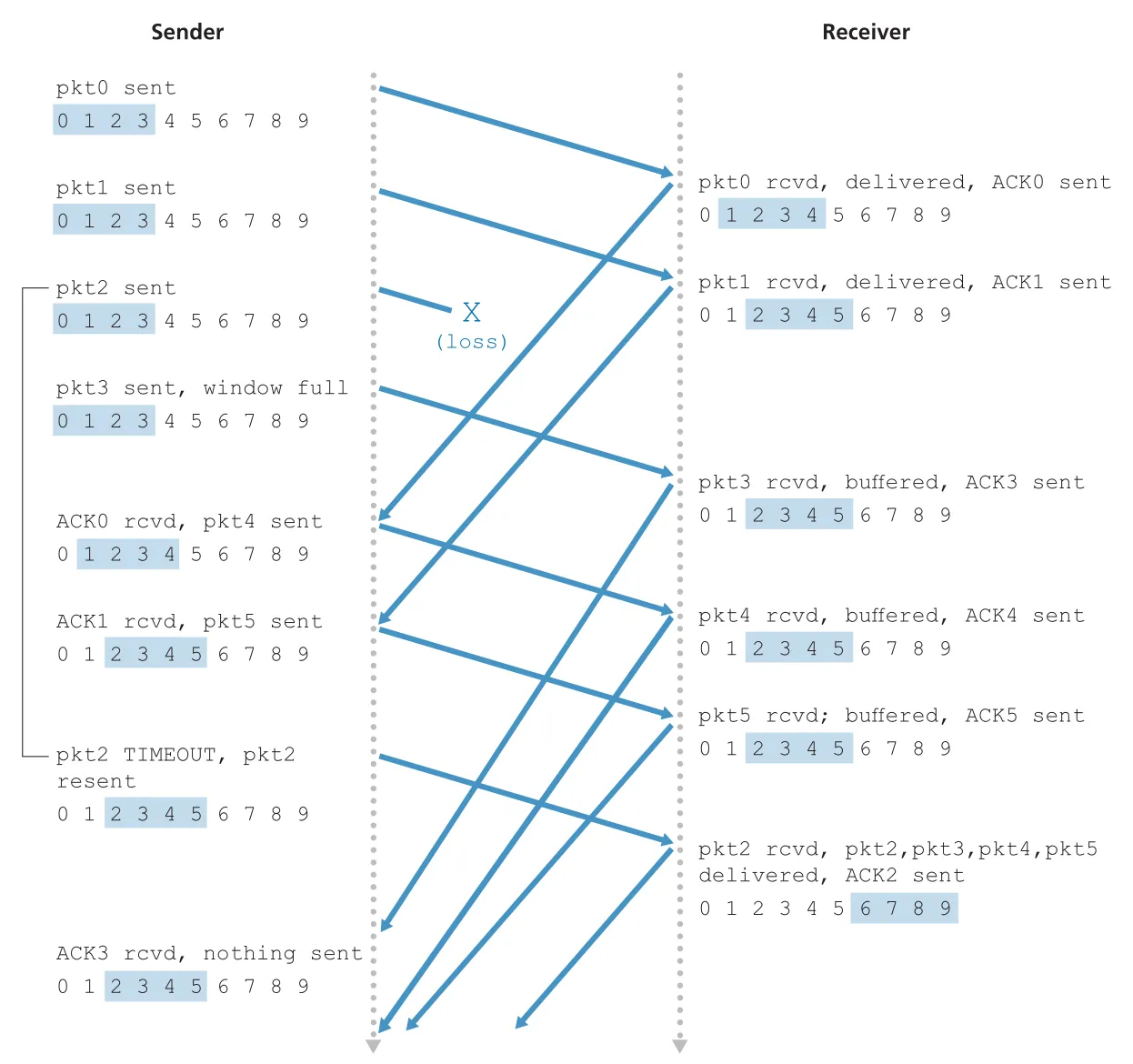 Figure 3.26 · PDF p. 234 · packet 2 loss 상황에서 SR receiver가 packets 3, 4, 5를 buffer하고, packet 2가 도착하자 함께 in-order deliver하는 흐름
SR receiver가 이미 받은 packet을 다시 ACK해야 하는 경우도 중요하다. sender의 ACK가 lost되면 sender는 packet을 retransmit할 수 있다. receiver가 “이미 받은 packet”이라고 무시하면 sender의 window가 영원히 움직이지 않을 수 있다. 그래서 receiver는 일정 범위의 previously received packets에 대해서도 ACK를 다시 보낸다.
SR window size 제약과 sequence number ambiguity
SR은 sender와 receiver windows가 항상 일치하지 않는다. 이 때문에 finite sequence number space에서는 ambiguity가 생길 수 있다. window size가 너무 크면 receiver는 동일한 sequence number를 가진 packet이 old retransmission인지 new data인지 구분하지 못한다.
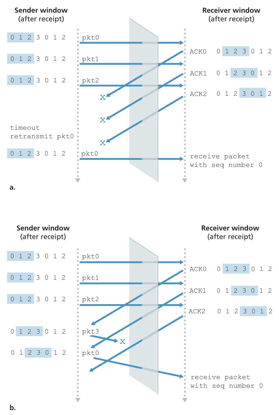 Figure 3.27 · PDF p. 236 · SR에서 window가 너무 크면 sequence number 0이 old retransmission인지 new packet인지 receiver가 구분할 수 없는 문제
핵심 조건은 다음과 같다.
이 조건은 reused sequence number가 아직 network 안에 남아 있는 old packet과 충돌하지 않게 하기 위한 것이다. 실제 network에서는 packet reordering도 가능하므로, protocol은 sequence number를 재사용하기 전에 이전 packet이 network에서 사라졌다고 볼 수 있는 maximum packet lifetime도 고려한다. TCP high-speed extensions에서는 packet lifetime을 대략 수분 단위로 가정하는 맥락이 나온다.
reliable data transfer mechanisms 요약
| Mechanism | Use |
|---|---|
checksum | transmitted packet의 bit errors detection |
timer | packet 또는 ACK loss 가능성에 대한 timeout/retransmission |
sequence number | lost packet gap, duplicate packet, ordering 확인 |
acknowledgment | receiver가 packet/set of packets를 correct receipt로 알림 |
negative acknowledgment | receiver가 특정 packet이 잘못 수신됐음을 알림 |
window, pipelining | multiple unacknowledged packets를 허용해 utilization 개선 |
이 메커니즘들은 TCP에서 그대로 또는 변형되어 사용된다. GBN에 가까운 cumulative ACK, SR에 가까운 selective recovery 아이디어, timeout, sequence number, buffering이 모두 TCP reliable data transfer의 기반이 된다.
3.5 Connection-Oriented Transport: TCP
TCP(Transmission Control Protocol)는 Internet의 connection-oriented, reliable transport protocol이다. TCP reliable data transfer는 앞 절의 원리를 실제 protocol에 넣은 것이다. error detection, retransmissions, cumulative acknowledgments, timers, sequence/acknowledgment number fields가 모두 TCP에서 사용된다.
TCP connection: circuit이 아니라 end-system state
TCP가 connection-oriented라는 말은 data를 보내기 전에 두 application processes가 preliminary segments를 주고받아 data transfer parameters와 TCP state variables를 초기화한다는 뜻이다. 하지만 TCP connection은 circuit-switched network의 TDM/FDM circuit이 아니다. routers와 link-layer switches는 TCP connection state를 유지하지 않으며, TCP connection을 “보는” 것이 아니라 IP datagrams만 forwarding한다.
TCP connection은 다음 성질을 가진다.
| 성질 | 의미 |
|---|---|
logical connection | common state는 양 끝 end systems의 TCP에만 존재 |
full-duplex service | A→B data와 B→A data가 같은 connection에서 동시에 흐를 수 있음 |
point-to-point | 하나의 sender와 하나의 receiver 사이 connection, multicast 불가 |
three-way handshake | connection establishment에 세 TCP segments 사용 |
client application이 clientSocket.connect((serverName, serverPort))를 호출하면 client TCP가 server TCP와 connection establishment를 시작한다. 세 segments가 오가기 때문에 이 절차를 three-way handshake라고 부른다. 처음 두 segments에는 application payload가 없고, 세 번째 segment는 payload를 가질 수 있다.
TCP buffers, MSS, MTU
connection이 established되면 application은 socket으로 byte stream을 넘긴다. TCP는 이 data를 바로 network로 밀어 넣는 것이 아니라 connection의 send buffer에 둔다. TCP는 적절한 시점에 send buffer에서 chunks를 꺼내 TCP header를 붙여 segments를 만들고 IP로 넘긴다. receiver TCP는 segment data를 receive buffer에 넣고, receiving application은 socket을 통해 stream을 읽는다.
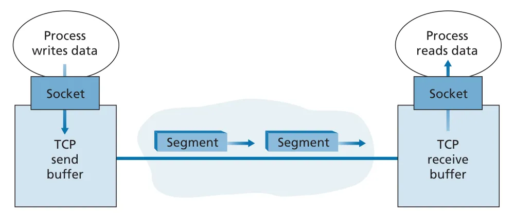 Figure 3.28 · PDF p. 240 · TCP connection 양끝의 send buffer와 receive buffer를 통해 byte stream이 이동하는 구조
MSS(maximum segment size)는 TCP segment의 data field에 넣을 수 있는 application-layer data의 최대 크기다. confusing하지만 MSS는 TCP header까지 포함한 전체 segment size가 아니다. 보통 local host가 보낼 수 있는 largest link-layer frame size인 MTU(maximum transmission unit)를 기준으로, IP/TCP headers까지 한 link-layer frame에 들어가도록 MSS를 정한다. Ethernet/PPP MTU가 1500 bytes일 때 typical MSS는 1460 bytes다.
TCP segment structure
TCP segment는 header fields와 data field로 구성된다. data field에는 application byte stream의 일부가 들어가고, MSS가 그 최대 크기를 제한한다. TCP header는 보통 20 bytes이며, UDP header 8 bytes보다 크다.
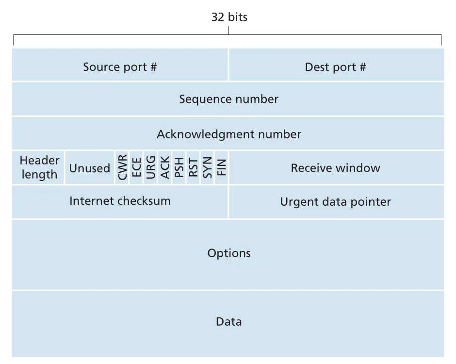 Figure 3.29 · PDF p. 242 · TCP segment header의 port, sequence number, acknowledgment number, receive window, flags, checksum, options fields
핵심 TCP header fields는 다음과 같다.
| Field | 역할 |
|---|---|
source port #, destination port # | multiplexing/demultiplexing |
sequence number | 이 segment data의 first byte number |
acknowledgment number | receiver가 다음에 기대하는 byte number |
receive window | receiver가 받아들일 수 있는 bytes 수, flow control |
header length | TCP header length, 32-bit words 단위 |
options | MSS negotiation, window scaling, timestamp 등 |
ACK flag | acknowledgment field가 valid함 |
SYN, FIN, RST | connection setup/teardown/reset |
CWR, ECE | Explicit Congestion Notification(ECN) |
checksum | segment error detection |
PSH, URG, urgent data pointer도 있지만 실제로는 거의 쓰이지 않는다. 시험/면접에서는 sequence number, acknowledgment number, receive window, SYN/FIN/ACK, checksum이 훨씬 중요하다.
sequence number: segment 번호가 아니라 byte 번호
TCP는 data를 unstructured but ordered byte stream으로 본다. 따라서 TCP sequence number는 packet/segment 번호가 아니라 byte stream 안의 byte 번호다. segment의 sequence number는 그 segment data field의 첫 번째 byte 번호다.
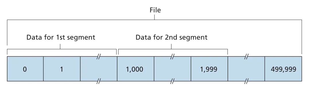 Figure 3.30 · PDF p. 243 · TCP가 file byte stream을 MSS 단위 segments로 나누고 first byte number를 sequence number로 사용하는 방식
예를 들어 500,000 bytes file을 MSS 1,000 bytes로 보내고 first byte number가 0이라면, TCP는 500 segments를 만든다. 첫 segment의 sequence number는 0, 두 번째는 1000, 세 번째는 2000이다.
acknowledgment number: next expected byte
TCP acknowledgment number는 receiver가 다음에 기대하는 byte의 sequence number다. Host A가 Host B로부터 bytes 0-535를 받았다면, A가 B로 보내는 next ACK number는 536이다. bytes 900-1000을 이미 out of order로 받았더라도 bytes 536-899가 비어 있다면 ACK는 여전히 536이다. 그래서 TCP ACK는 기본적으로 cumulative acknowledgment다.
TCP RFCs는 out-of-order segments를 받았을 때 receiver가 반드시 어떻게 해야 하는지 강제하지 않는다. 단순히 discard할 수도 있지만, 실제 구현은 보통 out-of-order bytes를 buffer하고 missing bytes가 도착하면 stream gap을 채운다. 이는 bandwidth 측면에서 효율적이다.
TCP connection의 양방향 data flow는 서로 독립적인 sequence number space를 가진다. 또한 connection 시작 시 양쪽은 initial sequence number를 random하게 고른다. 이는 이전 connection의 old segment가 network 안에 남아 있다가 같은 host/port pair의 새 connection에서 valid segment로 오인되는 가능성을 줄이기 위해서다.
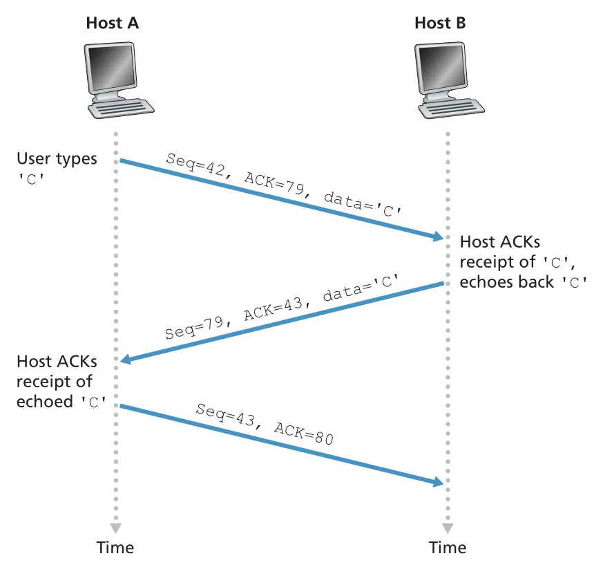 Figure 3.31 · PDF p. 245 · Telnet에서 한 글자 C가 오갈 때 sequence number와 acknowledgment number가 어떻게 증가하는지
Telnet 예시는 piggybacking도 보여 준다. client가 C 한 byte를 seq 42로 보내면 server는 ACK 43을 보내며 동시에 echo data C를 seq 79로 보낼 수 있다. 이때 ACK가 data segment에 함께 실리므로 piggybacked acknowledgment라고 한다. client가 server의 echoed C를 받으면 ACK 80을 보내고, 이 segment는 data field가 비어 있어도 TCP header에는 sequence number가 존재한다.
RTT estimation과 TimeoutInterval
TCP는 lost segment recovery를 위해 timeout/retransmit mechanism을 쓴다. timeout interval은 connection RTT보다 커야 unnecessary retransmission을 피할 수 있지만, 너무 크면 진짜 loss recovery가 늦어진다. 그래서 TCP는 RTT를 측정하고 fluctuation도 함께 반영한다.
SampleRTT는 segment를 IP로 넘긴 시점부터 그 segment에 대한 ACK가 도착할 때까지의 시간이다. 대부분의 TCP 구현은 한 번에 하나의 SampleRTT만 측정하며, retransmitted segment에 대해서는 SampleRTT를 계산하지 않는다. retransmission된 segment의 ACK가 original에 대한 ACK인지 retransmission에 대한 ACK인지 모호하기 때문이다.
TCP는 EstimatedRTT를 exponential weighted moving average(EWMA)로 갱신한다.
최근 SampleRTT에 더 큰 의미를 주되, single sample fluctuation에 지나치게 흔들리지 않게 smoothing한다.
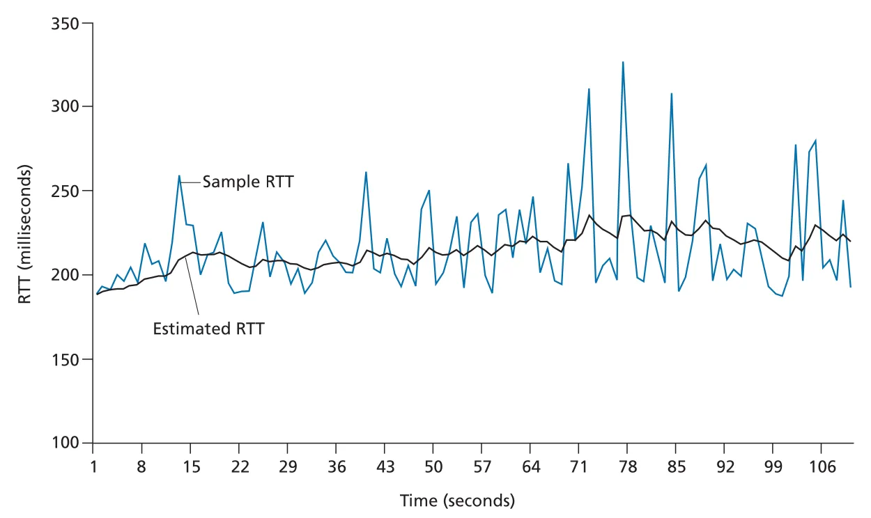 Figure 3.32 · PDF p. 249 · SampleRTT fluctuations를 EWMA EstimatedRTT가 smoothing하는 모습
RTT variability는 DevRTT로 추정한다.
최종 retransmission timeout은 다음처럼 정한다.
margin인 는 RTT fluctuation이 클 때 timeout을 더 넉넉하게 잡고, fluctuation이 작을 때 빠르게 loss recovery하도록 줄어든다. timeout이 발생하면 TCP는 premature timeout 연쇄를 피하기 위해 TimeoutInterval을 일시적으로 double한다. 이후 새 SampleRTT로 EstimatedRTT가 갱신되면 다시 위 공식으로 계산한다.
TCP reliable data transfer: IP 위에 reliable byte stream 만들기
IP는 delivery, ordering, integrity를 보장하지 않는 best-effort service다. TCP segment도 IP datagram에 실려 이동하므로 loss, reordering, bit corruption을 겪을 수 있다. TCP reliable data transfer service는 receiving process가 TCP receive buffer에서 읽는 byte stream이 sender가 보낸 byte stream과 정확히 같도록 만든다. 즉 uncorrupted, no gaps, no duplication, in sequence를 보장한다.
이론적으로는 unacknowledged segment마다 timer를 둘 수 있지만, TCP recommended timer management는 여러 outstanding segments가 있어도 single retransmission timer를 사용한다. 이 timer는 oldest unacknowledged segment와 관련된 timer처럼 생각하면 된다.
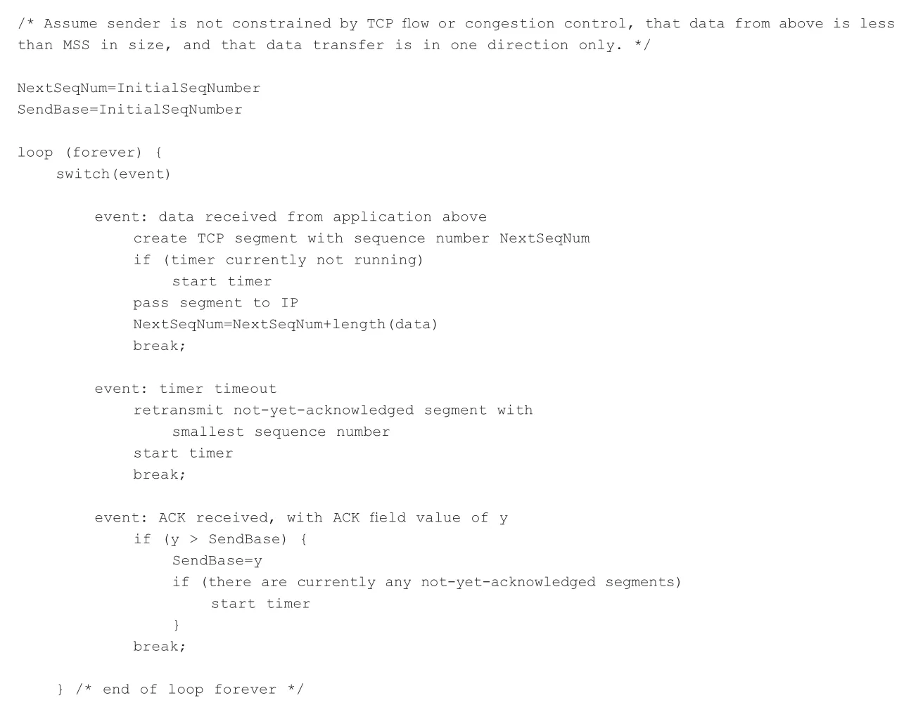 Figure 3.33 · PDF p. 250 · simplified TCP sender가 application data, timeout, ACK received events에 반응하는 방식
simplified TCP sender의 핵심 state variables는 다음과 같다.
| Variable | 의미 |
|---|---|
NextSeqNum | 다음에 보낼 byte의 sequence number |
SendBase | oldest unacknowledged byte의 sequence number |
TimeoutInterval | current retransmission timer interval |
sender event별 동작은 다음처럼 정리된다.
| Event | TCP sender action |
|---|---|
| data received from application | segment 생성, sequence number=NextSeqNum, timer가 꺼져 있으면 start, IP로 전달, NextSeqNum 증가 |
| timer timeout | smallest sequence number를 가진 not-yet-acknowledged segment retransmit, timer restart |
ACK with value y received | 이면 cumulative ACK로 보고 , outstanding segment가 있으면 timer restart |
lost ACK와 cumulative ACK examples
첫 번째 예시는 data segment는 도착했지만 ACK가 lost된 경우다. Host A가 seq 92, data 8 bytes를 보내면 Host B는 ACK 100을 보낸다. ACK가 lost되면 A의 timer가 expire되고 A는 같은 segment를 retransmit한다. B는 sequence number를 보고 이미 받은 bytes임을 알며 duplicate data를 discard한다.
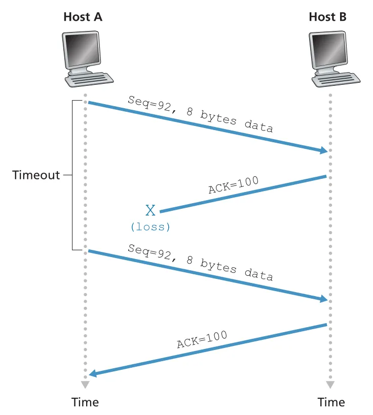 Figure 3.34 · PDF p. 252 · data는 도착했지만 ACK가 lost되어 timeout 후 같은 segment가 재전송되는 상황
두 번째 예시는 A가 seq 92/8 bytes와 seq 100/20 bytes 두 segments를 back-to-back으로 보냈고, 두 ACK가 timeout 전에 도착하지 않은 경우다. timeout이 나면 A는 oldest unacknowledged segment인 seq 92만 retransmit한다. 그 뒤 ACK 120이 새 timeout 전에 도착하면 seq 100 segment는 retransmit하지 않는다.
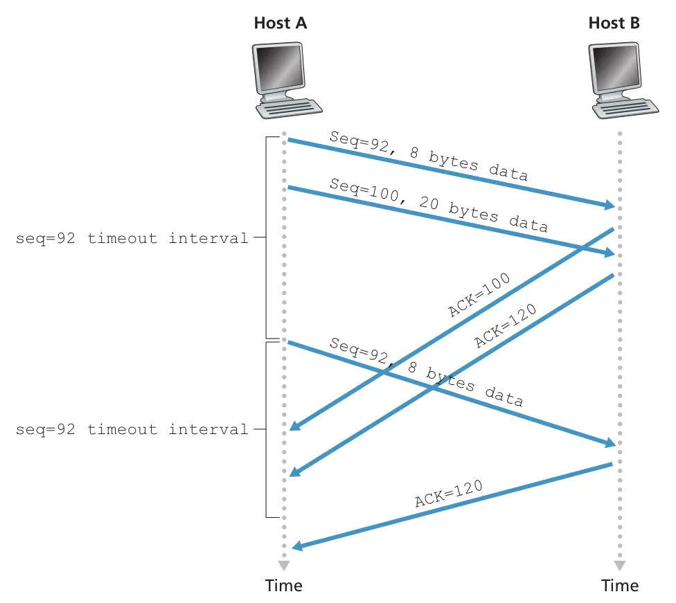 Figure 3.35 · PDF p. 253 · ACK들이 늦게 도착하더라도 cumulative ACK 120이 오면 segment 100 재전송을 피하는 상황
세 번째 예시는 첫 ACK 100은 lost되지만, ACK 120이 timeout 전에 도착하는 경우다. ACK 120은 “byte 119까지 모두 받았고 다음은 120을 기대한다”는 cumulative acknowledgment이므로 A는 seq 92와 seq 100 모두 재전송하지 않는다.
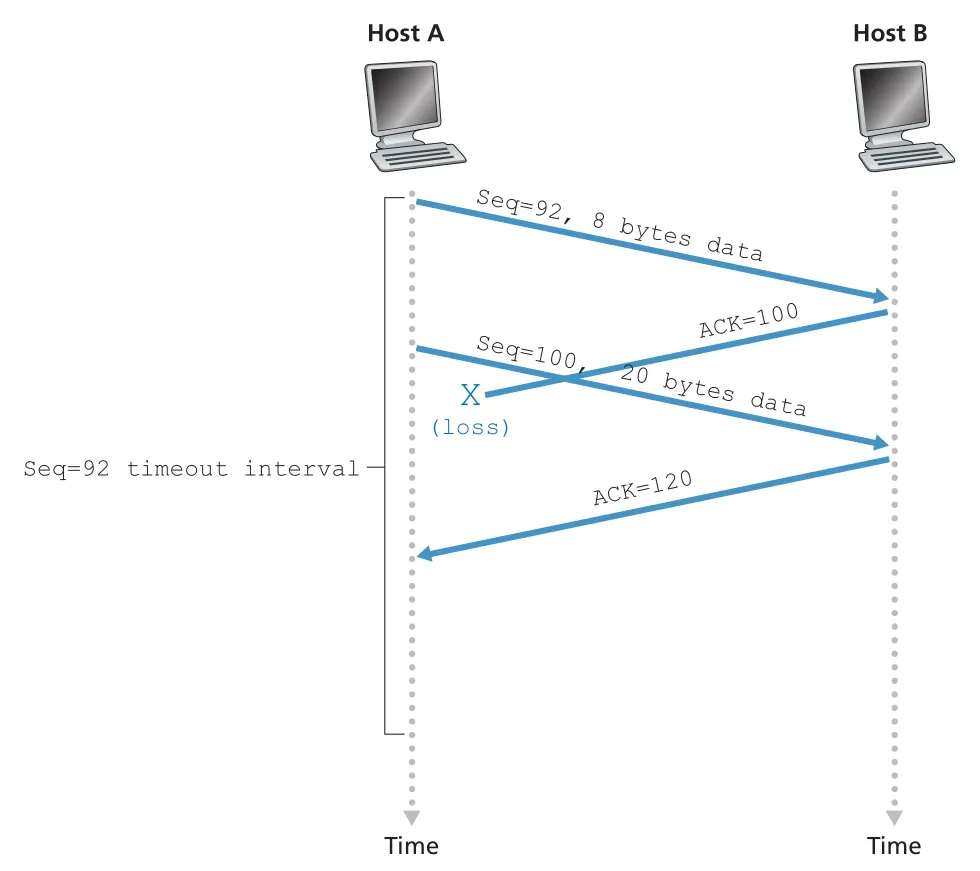 Figure 3.36 · PDF p. 254 · cumulative ACK가 이전 segment의 lost ACK를 덮어 재전송을 피하는 방식
timeout doubling: 조심스럽게 재전송하기
TCP는 timeout이 발생할 때마다 not-yet-acknowledged segment 중 smallest sequence number segment를 retransmit한다. 다만 다음 timeout interval은 기존 를 바로 쓰지 않고 이전 interval의 두 배로 늘린다. 예를 들어 0.75초 timeout 후 retransmit했다면 다음은 1.5초, 다시 timeout이면 3.0초로 증가한다.
이 exponential backoff는 limited congestion control 성격을 가진다. timeout은 network congestion 때문에 packet drop이나 long queuing delay가 생겼을 가능성이 높다. 그때 sender가 짧은 간격으로 계속 retransmit하면 congestion을 더 악화시킨다. TCP는 timeout 간격을 늘려 network에 더 예의 있게 동작한다.
duplicate ACK와 fast retransmit
timeout 기반 recovery의 단점은 timeout period가 길 수 있다는 것이다. TCP sender는 timeout 전에 loss를 감지할 수 있는데, 그 신호가 duplicate ACK다. duplicate ACK는 이미 ACK한 data를 다시 ACK하는 segment다.
receiver가 expected sequence number보다 큰 segment를 받으면 data stream에 gap이 있음을 안다. TCP는 explicit NAK를 쓰지 않으므로 receiver는 마지막 in-order byte 다음 값을 ACK number로 다시 보낸다. sender가 같은 ACK를 여러 번 받으면 그 ACK 다음 segment가 missing됐다고 추론할 수 있다.
TCP receiver ACK policy의 핵심은 다음과 같다.
| Receiver event | ACK action |
|---|---|
| expected in-order segment 도착, 이전 data 모두 ACK됨 | delayed ACK: 최대 500 ms 기다렸다가 ACK |
| expected in-order segment 도착, ACK 대기 중인 in-order segment 있음 | 즉시 cumulative ACK |
| higher-than-expected out-of-order segment 도착 | 즉시 duplicate ACK, next expected byte를 ACK |
| gap을 일부/전부 채우는 segment 도착 | lower end of gap에서 시작하면 즉시 ACK |
sender가 같은 data에 대한 three duplicate ACKs를 받으면, 그 ACKed byte 다음 segment가 lost됐다고 보고 timer expiration 전에 retransmit한다. 이것이 fast retransmit이다.
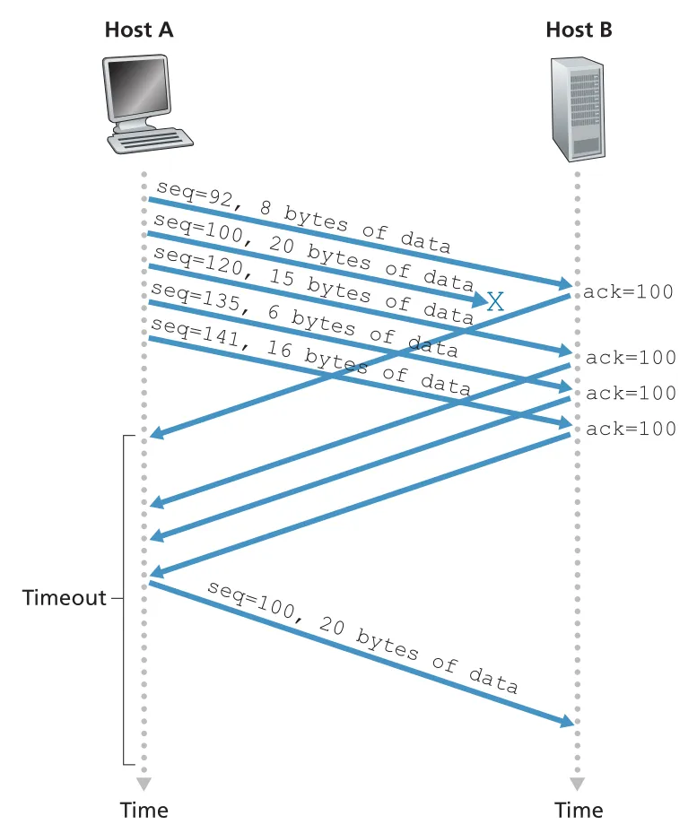 Figure 3.37 · PDF p. 256 · segment loss 후 세 duplicate ACKs를 받은 sender가 timeout 전에 missing segment를 retransmit하는 흐름
fast retransmit은 다음처럼 생각할 수 있다.
on ACK y:
  if y > SendBase:
      SendBase = y
      reset duplicate ACK count
  else:
      duplicateACK[y] += 1
      if duplicateACK[y] == 3:
          retransmit segment with sequence number y
TCP는 GBN인가 SR인가
TCP는 순수한 GBN도, 순수한 SR도 아니다. TCP ACK는 cumulative이고, sender가 최소한 SendBase와 NextSeqNum을 유지한다는 점에서는 GBN-like이다. 하지만 많은 TCP implementations는 out-of-order segments를 receiver buffer에 저장하고, ACK loss 상황에서 GBN처럼 뒤쪽 모든 segments를 무조건 재전송하지 않는다.
또한 SACK(selective acknowledgment) option을 쓰면 receiver가 out-of-order segments를 선택적으로 알릴 수 있고, sender는 이미 selectively acknowledged된 segments를 건너뛰고 missing segments만 retransmit할 수 있다. 이 경우 TCP는 SR-like recovery에 더 가까워진다. 따라서 TCP error recovery는 GBN과 SR의 hybrid로 보는 것이 가장 정확하다.
TCP flow control: receiver buffer를 넘치지 않게 하기
TCP connection 양끝에는 receive buffer가 있다. segment가 correct and in sequence로 도착하면 TCP는 data를 receive buffer에 넣고, application process는 그 buffer에서 data를 읽는다. application이 느리게 읽으면 sender가 빠르게 보낸 data가 receiver buffer를 overflow시킬 수 있다.
TCP flow control은 sender가 receiver buffer를 넘치게 하지 않도록 sending rate를 receiving application의 reading rate에 맞추는 speed-matching service다. 이것은 congestion control과 다르다. flow control은 receiver buffer 보호이고, congestion control은 network 내부 routers/links의 congestion을 피하거나 줄이는 것이다.
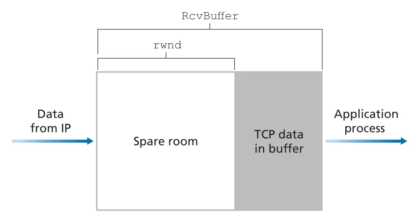 Figure 3.38 · PDF p. 259 · RcvBuffer 안에서 TCP data가 차지한 영역과 spare room인 receive window(rwnd)
Host B가 Host A로부터 file을 받을 때, B의 receive buffer 크기를 RcvBuffer라고 하자.
(receive window)는 receiver buffer에 남은 spare room이다. Host B는 A로 보내는 모든 TCP segments의 receive window field에 현재 값을 넣어 광고한다. Host A는 outstanding unacknowledged data 양을 이 값 이하로 유지해야 한다.
minor technical problem은 일 때 생긴다. B가 receive buffer full을 알린 뒤 B가 A로 보낼 data나 ACK가 없으면, application이 buffer를 비워도 A에게 새 값이 전달되지 않을 수 있다. 그래서 TCP는 receiver window가 0일 때도 sender가 1-byte data segment를 계속 보내도록 요구한다. 이 probe가 ACK되면서 eventually nonzero 가 sender에게 전달된다.
UDP는 flow control을 제공하지 않는다. UDP receiver 앞의 finite buffer에서 application이 segments를 충분히 빨리 읽지 못하면 buffer overflow로 segments가 drop될 수 있다.
TCP connection management: three-way handshake
TCP connection establishment는 perceived delay에도 영향을 주고, SYN flood 같은 attack surface도 만든다. client가 server process에 connection을 열고 싶으면 client TCP와 server TCP가 세 단계로 handshake한다.
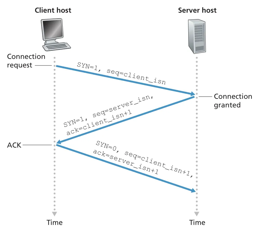 Figure 3.39 · PDF p. 261 · client SYN, server SYNACK, client ACK로 TCP connection을 여는 three-way handshake
three-way handshake의 message flow는 다음과 같다.
1. Client -> Server: SYN=1, seq=client_isn
2. Server -> Client: SYN=1, seq=server_isn, ack=client_isn+1
3. Client -> Server: SYN=0, seq=client_isn+1, ack=server_isn+1
1단계에서 client는 SYN segment를 보낸다. application payload는 없고, SYN bit가 1이며, random initial sequence number인 client_isn을 sequence number field에 넣는다. 2단계에서 server는 buffers와 variables를 allocate하고 SYNACK segment를 보낸다. 이 segment는 SYN=1, ack=client_isn+1, seq=server_isn을 담는다. 3단계에서 client도 connection resources를 allocate하고 ack=server_isn+1을 담은 ACK segment를 보낸다. 이때부터 SYN bit는 0이며, 세 번째 segment는 client-to-server data를 payload로 포함할 수 있다.
server가 third handshake step 전에 buffers와 variables를 allocate한다는 점이 SYN flood attack의 기반이다. attacker가 많은 SYN을 보내고 마지막 ACK를 보내지 않으면 half-open connections가 server resources를 소모한다. SYN cookies는 server가 SYN 수신 시 state를 저장하지 않고, source/destination IP/port와 secret으로 만든 cookie를 initial sequence number에 encoding했다가, legitimate ACK가 오면 검증 후에야 connection state를 allocate하는 방어다.
TCP connection closing과 states
TCP connection은 양쪽 어느 process든 close할 수 있다. client가 close한다고 하면 client TCP는 FIN=1 segment를 보내고, server는 ACK를 보낸다. server도 close 준비가 되면 자신의 FIN=1 segment를 보내고, client가 이를 ACK한다. 그 뒤 resources가 deallocated된다.
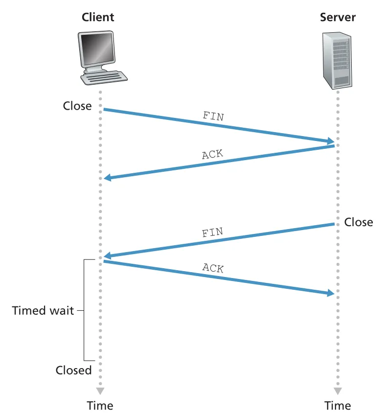 Figure 3.40 · PDF p. 262 · FIN/ACK exchange로 TCP connection 양방향을 닫는 흐름
client TCP의 typical state path는 다음과 같다.
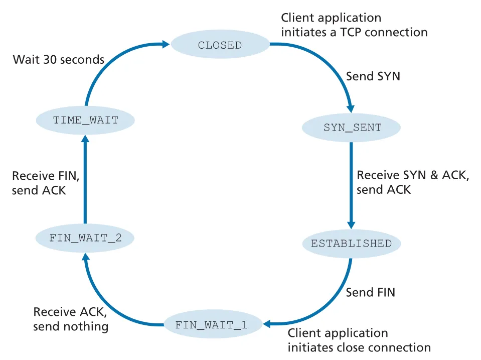 Figure 3.41 · PDF p. 263 · client-side TCP가 CLOSED, SYN_SENT, ESTABLISHED, FIN_WAIT, TIME_WAIT를 거치는 전형적 상태 흐름
CLOSED
  -> SYN_SENT        after sending SYN
  -> ESTABLISHED     after receiving SYNACK and sending ACK
  -> FIN_WAIT_1      after client application initiates close and sends FIN
  -> FIN_WAIT_2      after receiving ACK for FIN
  -> TIME_WAIT       after receiving server FIN and sending final ACK
-> CLOSED after waiting for possible final ACK retransmissionTIME_WAIT는 final ACK가 lost될 경우 client가 다시 ACK를 보낼 수 있게 하는 대기 상태다. 구현마다 30초, 1분, 2분 같은 값이 사용된다.
server-side TCP의 typical state path는 다음과 같다.
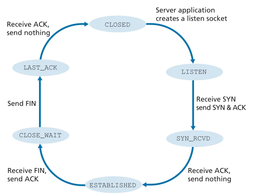 Figure 3.42 · PDF p. 264 · server-side TCP가 LISTEN, SYN_RCVD, ESTABLISHED, CLOSE_WAIT, LAST_ACK를 거치는 전형적 상태 흐름
CLOSED
  -> LISTEN          server application creates listen socket
  -> SYN_RCVD        after receiving SYN and sending SYNACK
  -> ESTABLISHED     after receiving ACK
  -> CLOSE_WAIT      after receiving client FIN and sending ACK
  -> LAST_ACK        after sending server FIN
  -> CLOSED          after receiving ACK for server FIN
RST와 nmap port scanning
host가 자신이 가진 socket과 matching되지 않는 TCP segment를 받으면 RST flag가 set된 reset segment를 보낼 수 있다. 예를 들어 destination port 80으로 SYN이 왔지만 Web server가 port 80에서 listen하지 않으면 RST를 보내 “그 socket이 없다, 다시 보내지 말라”고 알린다. UDP에서 destination port에 matching되는 socket이 없으면 TCP RST가 아니라 ICMP datagram이 사용된다.
nmap은 TCP connection-management behavior를 이용해 port scanning을 수행한다. target port 6789로 SYN을 보냈을 때 가능한 결과는 다음과 같다.
| Result | 의미 |
|---|---|
SYNACK 수신 | target host에서 해당 TCP port가 open |
RST 수신 | host까지 도달했고 port는 closed, firewall이 막지는 않음 |
| no response | intervening firewall이 SYN을 blocked했을 가능성 |
이처럼 TCP connection management는 성능뿐 아니라 security diagnosis와 attack reconnaissance에도 직접 연결된다.
3.6 Principles of Congestion Control
앞 절까지의 reliable data transfer는 packet loss가 생겼을 때 segment를 다시 보내는 방법을 다루었다. 하지만 실제 네트워크에서 loss의 흔한 원인은 router buffer overflow이고, retransmission은 congestion의 증상만 고친다. 원인은 너무 많은 source가 너무 높은 rate로 데이터를 밀어 넣는 것이다. 따라서 congestion control은 sender의 전송 속도를 줄이거나 조절해서 네트워크 내부의 queue, drop, wasted bandwidth를 막는 문제다.
3.6.1 The Causes and the Costs of Congestion
Scenario 1: Two Senders, a Router with Infinite Buffers. 두 connection이 하나의 bottleneck link capacity 을 공유하고, router buffer가 무한하다고 하자. 각 sender가 application original data를 bytes/sec로 보낼 때, 이면 receiver throughput 은 거의 과 같다. 그러나 두 connection이 link를 나누므로 한 connection의 steady-state throughput은 를 넘을 수 없다.
문제는 throughput 한계보다 delay다. 이 에 가까워질수록 queue가 길어지고 average delay가 급격히 커진다. 무한 buffer 가정에서는 packet drop은 없지만, 로 오래 동작하면 평균 queue length와 delay가 무한대로 발산한다. 첫 번째 congestion cost는 link capacity에 가까워질수록 발생하는 large queuing delay다.
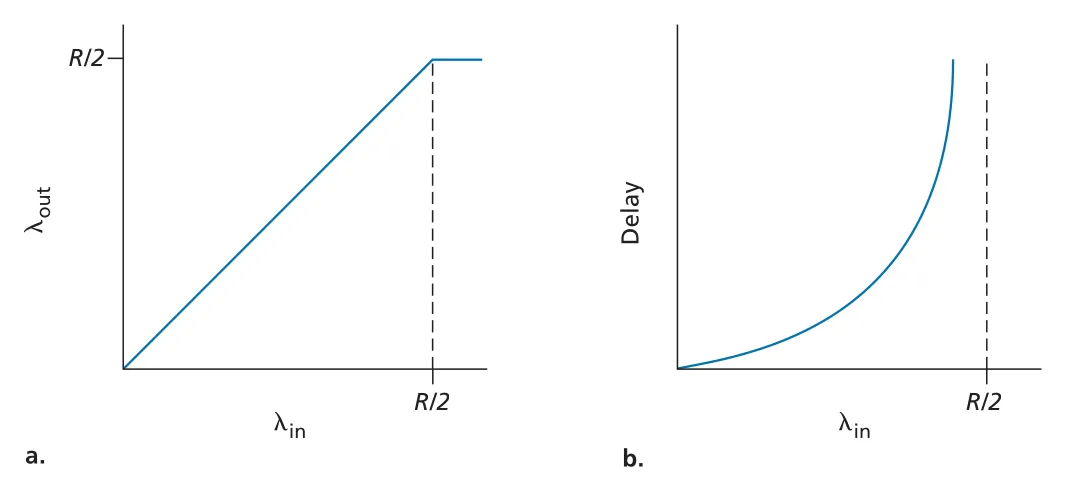 Figure 3.44 · PDF p. 268 · infinite buffer에서 sending rate가 link share에 접근할 때 throughput은 포화되고 delay는 폭증한다
Scenario 2: Two Senders and a Router with Finite Buffers. 현실적인 router buffer는 finite이므로 buffer가 꽉 찬 상태에서 도착한 packet은 dropped 된다. reliable transport는 drop된 segment를 retransmit하므로 rate를 두 가지로 구분해야 한다.
| 기호 | 의미 |
|---|---|
| application이 socket에 넣는 original data rate | |
| transport layer가 network에 넣는 offered load: original data + retransmitted data |
sender가 router buffer 여유를 완벽히 알고 loss 없이 보낸다면 이고 throughput도 이 된다. 하지만 실제로는 buffer overflow가 생기고, lost packet을 보상하려면 retransmission이 필요하다. 이때 같은 link capacity 중 일부가 original data가 아니라 retransmitted data를 운반하는 데 쓰인다. 두 번째 congestion cost는 buffer overflow 때문에 retransmission traffic이 필요해지는 것이다.
더 나쁜 경우는 premature timeout이다. packet이 lost 된 것이 아니라 queue에서 오래 지연되고 있을 뿐인데 sender가 timeout으로 다시 보내면, original packet과 retransmitted packet이 모두 receiver에 도착할 수 있다. receiver는 duplicate를 버리므로 router가 duplicate copy를 전달하는 데 쓴 bandwidth는 낭비된다. 세 번째 congestion cost는 unneeded retransmission이 link bandwidth를 불필요한 duplicate forwarding에 쓰게 만드는 것이다.
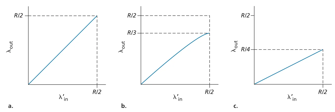 Figure 3.46 · PDF p. 270 · finite buffer에서 retransmission 방식에 따라 offered load 대비 useful throughput이 달라진다
Scenario 3: Four Senders, Routers with Finite Buffers, and Multihop Paths. multihop path에서는 packet이 중간 link들을 이미 지나온 뒤 downstream router에서 drop될 수 있다. 예를 들어 A-C traffic이 R1을 지나 R2에서 B-D traffic과 경쟁하다 drop되면, R1이 그 packet을 R2까지 전달하는 데 쓴 transmission capacity가 모두 wasted work가 된다.
offered load가 작을 때는 증가가 throughput 증가로 이어진다. 그러나 모든 connection의 이 매우 커지면, bottleneck router의 buffer를 경쟁 traffic이 즉시 채우고 특정 end-to-end connection의 throughput은 오히려 감소할 수 있다. 극단적으로 heavy traffic에서는 useful throughput이 0에 가까워질 수도 있다. 네 번째 congestion cost는 downstream drop이 upstream link capacity까지 낭비하게 만드는 것이다.
 Figure 3.48 · PDF p. 272 · multihop congestion에서는 offered load가 너무 커지면 throughput이 오히려 감소할 수 있다
congestion의 비용을 정리하면 다음과 같다.
| 상황 | 비용 |
|---|---|
| arrival rate가 service rate에 접근 | queueing delay 증가 |
| finite buffer overflow | dropped packet을 보상하기 위한 retransmission |
| premature timeout | duplicate packet 전달로 link bandwidth 낭비 |
| multihop downstream drop | 이미 사용한 upstream transmission capacity 낭비 |
3.6.2 Approaches to Congestion Control
congestion control 접근은 network layer가 transport layer에 explicit assistance를 주는지에 따라 나뉜다.
| 접근 | 핵심 방식 | 예 |
|---|---|---|
end-to-end congestion control | network가 명시적 feedback을 주지 않는다. end system이 packet loss, timeout, three duplicate ACKs, delay 증가 같은 관찰 가능한 현상으로 congestion을 추론한다. | Internet default TCP |
network-assisted congestion control | router가 congestion state를 sender 또는 receiver에 명시적으로 알려준다. 단순한 1-bit marking부터 지원 가능한 sending rate까지 다양하다. | ATM ABR, ECN |
network-assisted 방식의 feedback path는 두 가지다. 첫째, router가 sender에게 직접 choke packet 같은 direct feedback을 보낼 수 있다. 둘째, router가 sender에서 receiver로 가는 packet header를 mark하고, receiver가 그 표시를 다시 sender에게 알려줄 수 있다. 후자는 receiver를 거치므로 congestion indication이 sender에게 돌아오는 데 한 full RTT가 걸린다.
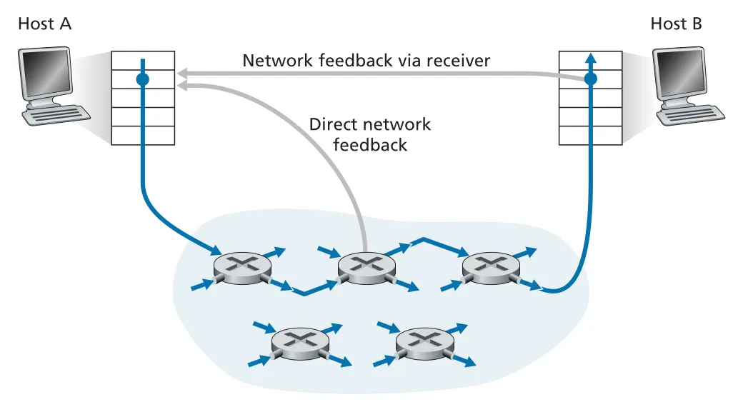 Figure 3.49 · PDF p. 274 · congestion indication은 router에서 sender로 직접 가거나 receiver를 거쳐 돌아갈 수 있다
3.7 TCP Congestion Control
TCP는 reliable transport service뿐 아니라 congestion-control mechanism도 제공한다. Classic TCP는 network-assisted feedback 없이 end-to-end congestion control을 수행한다. 즉 IP layer가 “지금 congested”라고 직접 알려주지 않아도, TCP sender가 timeout, three duplicate ACKs, ACK arrival pattern 같은 local observation으로 path 상태를 추론한다.
3.7.1 Classic TCP Congestion Control
TCP congestion control의 핵심 질문은 세 가지다.
| 질문 | TCP의 답 |
|---|---|
| sender rate를 어떻게 제한하는가? | congestion window (cwnd)로 outstanding data를 제한한다. |
| congestion을 어떻게 감지하는가? | loss event: timeout 또는 three duplicate ACKs를 congestion indication으로 본다. |
| rate를 어떻게 바꾸는가? | ACK가 오면 늘리고, loss event가 오면 줄이며, bandwidth probing을 반복한다. |
TCP sender는 flow control의 와 congestion control의 를 함께 만족해야 한다.
congestion control만 보려면 receive buffer가 충분히 크다고 가정해 constraint를 무시한다. 그러면 sender는 대략 한 RTT 동안 bytes를 보내고 ACK를 받으므로 sending rate는 다음처럼 근사된다.
ACK는 network가 segment를 destination까지 전달했다는 implicit positive signal이다. TCP는 ACK arrival을 이용해 를 키운다. 그래서 TCP는 ACK가 window 증가를 clocking한다는 의미에서 self-clocking이라고도 불린다. 반대로 timeout 또는 three duplicate ACKs는 path 어딘가의 router buffer overflow 가능성을 나타내는 implicit negative signal이다.
TCP의 rate 조절은 bandwidth probing이다. ACK가 오면 “아직 여유가 있나?” 하고 rate를 조금씩 높이고, loss event가 오면 “방금 congestion onset을 넘었다”고 보고 뒤로 물러난다. network와 sender들이 중앙에서 조율되는 것이 아니라 각 TCP sender가 local information으로 asynchronous하게 동작한다.
Slow Start
TCP connection이 시작되면 는 보통 로 초기화된다. 초기 sending rate는 정도라 작지만, slow start에서는 ACK 하나가 올 때마다 를 씩 늘린다. 첫 RTT에 1 segment를 보내고 ACK를 받으면 다음에는 2 segments, 그다음에는 4 segments처럼 매 RTT마다 대략 두 배가 된다. 이름은 slow start지만 증가율은 exponential이다.
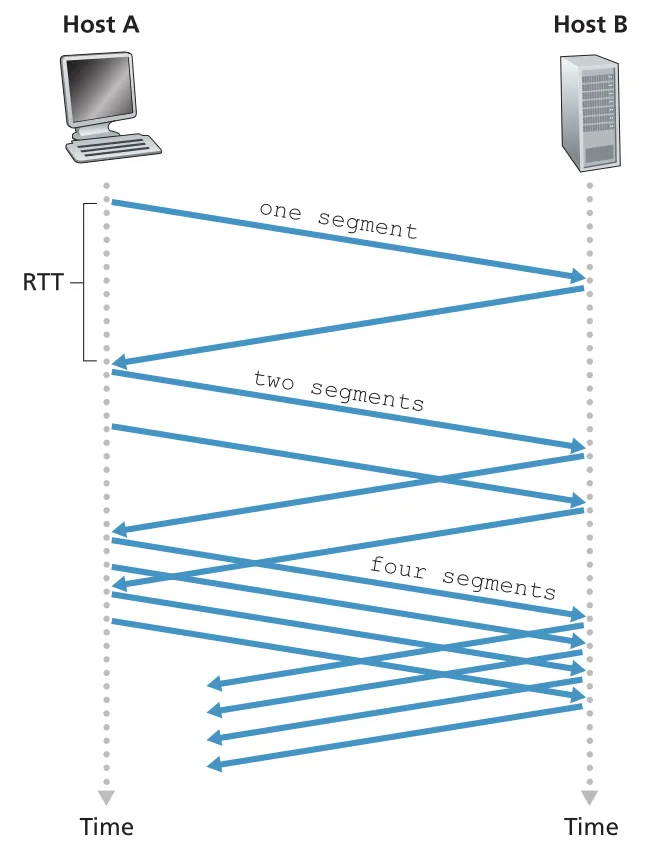 Figure 3.50 · PDF p. 277 · slow start에서 ACK가 도착할 때마다 cwnd가 늘어 매 RTT 전송량이 두 배로 증가한다
slow start가 끝나는 조건은 세 가지다.
| 종료 조건 | 동작 |
|---|---|
| timeout | , , slow start 재시작 |
| exponential growth를 멈추고 congestion avoidance로 전환 | |
| three duplicate ACKs | fast retransmit 후 fast recovery로 전환 |
ssthresh (slow start threshold)는 마지막 congestion detection 시점의 window 절반이다. 가 이 threshold에 도달했다면, 과거에 congestion이 발생한 크기에 가까워진 것이므로 더 이상 두 배씩 키우지 않고 조심스럽게 증가한다.
Congestion Avoidance
congestion avoidance에 들어갈 때 는 마지막 congestion window의 절반 근처다. 이 상태에서는 congestion이 가까울 수 있으므로 를 매 RTT마다 정도만 증가시킨다. 일반적으로 ACK 하나가 도착할 때마다 다음처럼 조금씩 더한다.
예를 들어 라면 한 RTT 동안 ACK가 약 10개 오고, 각 ACK가 씩 더해 전체적으로 한 RTT에 가 증가한다. timeout이 발생하면 slow start와 동일하게 , 로 줄인다. 그러나 three duplicate ACKs는 timeout보다 덜 심각한 신호로 본다. duplicate ACKs가 왔다는 것은 일부 segment는 receiver에 계속 도착하고 있다는 뜻이기 때문이다. 그래서 TCP Reno는 를 절반으로 줄인 뒤 fast recovery에 들어간다.
Fast Recovery, Tahoe, Reno
fast recovery에서는 missing segment에 대한 duplicate ACK가 추가로 올 때마다 를 씩 증가시킨다. missing segment에 대한 ACK가 도착하면 를 조정해 congestion avoidance로 돌아간다. timeout이 발생하면 더 강하게 반응해서 로 줄이고 slow start로 돌아간다.
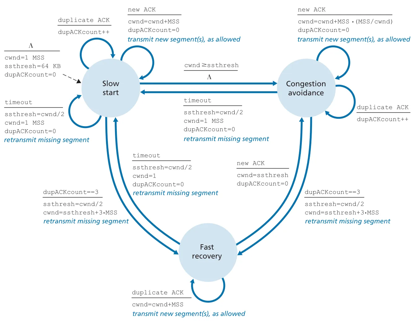 Figure 3.51 · PDF p. 279 · slow start, congestion avoidance, fast recovery 사이의 TCP congestion-control FSM
TCP Tahoe는 timeout이든 triple duplicate ACK든 loss event가 발생하면 무조건 로 줄이고 slow start로 돌아갔다. TCP Reno는 triple duplicate ACK의 경우 fast recovery를 사용해 더 덜 급격하게 줄인다. 그래서 같은 loss event 이후 Reno는 Tahoe보다 빠르게 window를 회복한다.
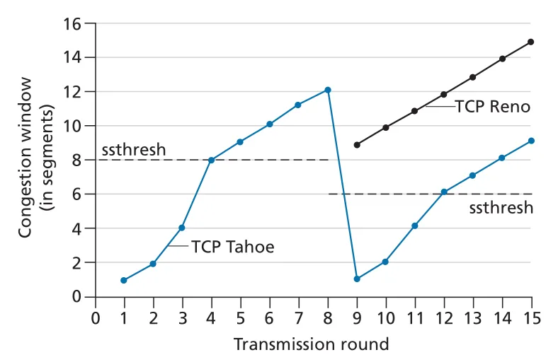 Figure 3.52 · PDF p. 281 · triple duplicate ACK 이후 Tahoe는 slow start로, Reno는 fast recovery로 진행한다
AIMD와 TCP CUBIC
초기 slow start를 제외하고, loss가 timeout이 아니라 triple duplicate ACK로 감지된다고 보면 TCP Reno의 핵심은 AIMD (additive-increase, multiplicative-decrease)다.
이 규칙은 sawtooth pattern을 만든다. TCP는 congestion window를 선형으로 올리며 available bandwidth를 probe하다가 loss event를 만나면 절반으로 줄이고, 다시 probe를 시작한다.
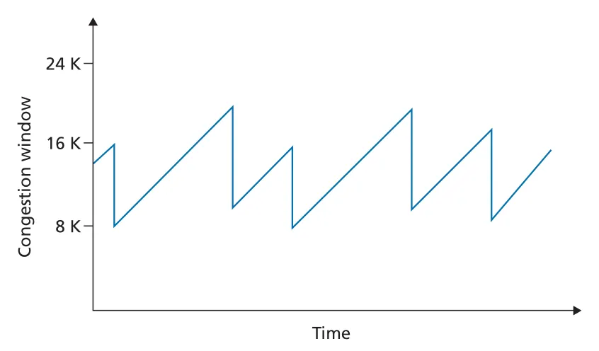 Figure 3.53 · PDF p. 282 · AIMD는 additive increase와 multiplicative decrease로 sawtooth window 변화를 만든다
TCP CUBIC은 Reno의 congestion avoidance가 너무 조심스럽다는 문제의식에서 나왔다. loss 직전 window를 라 하고, 앞으로 다시 에 도달할 시간점을 라고 할 때, CUBIC은 현재 시간 와 사이 거리의 cubic function으로 를 증가시킨다. 가 에서 멀면 빠르게 증가하고, 근처에서는 조심스럽게 증가한다. 가 되어도 loss가 없으면 다시 더 빠르게 증가해 새 operating point를 찾는다.
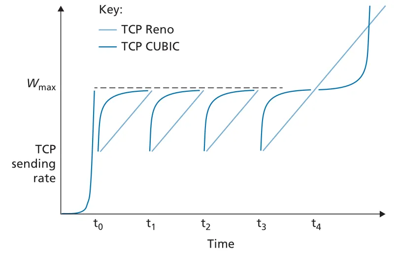 Figure 3.54 · PDF p. 283 · CUBIC은 loss 전 window 근처까지 빠르게 회복한 뒤 조심스럽게 probing한다
TCP Reno의 macroscopic throughput은 sawtooth를 평균낸 단순 모델로 볼 수 있다. loss 직전 window를 W라고 하면 rate는 대략 에서 사이를 선형 증가하므로 평균 throughput은 다음처럼 근사된다.
이 식은 TCP throughput이 뿐 아니라 RTT에도 강하게 의존한다는 점을 보여준다. 같은 bottleneck을 공유해도 RTT가 짧은 connection은 ACK clock이 더 빠르게 돌아 window를 더 빨리 키울 수 있다.
3.7.2 Network-Assisted Explicit Congestion Notification and Delay-Based Congestion Control
ECN (Explicit Congestion Notification)은 Internet에서 사용하는 network-assisted congestion control이다. IP datagram header의 Type of Service field 안에 있는 ECN bits를 이용해 router가 congestion onset을 표시한다. 핵심은 packet을 drop하기 전에 congestion을 mark할 수 있다는 점이다.
ECN 흐름은 다음과 같다.
- sender는 자신과 receiver가 ECN-capable임을 표시한다.
- congested router가 IP datagram의 ECN bits를 mark한다.
- receiver TCP가 marked datagram을 보고 ACK segment의
ECE (Explicit Congestion Notification Echo)bit를 set한다. - sender TCP는 ECE가 set된 ACK를 받으면 fast retransmit 때처럼 congestion window를 절반으로 줄인다.
- sender는 다음 sender-to-receiver TCP segment에서
CWR (Congestion Window Reduced)bit를 set해 반응했음을 알린다.
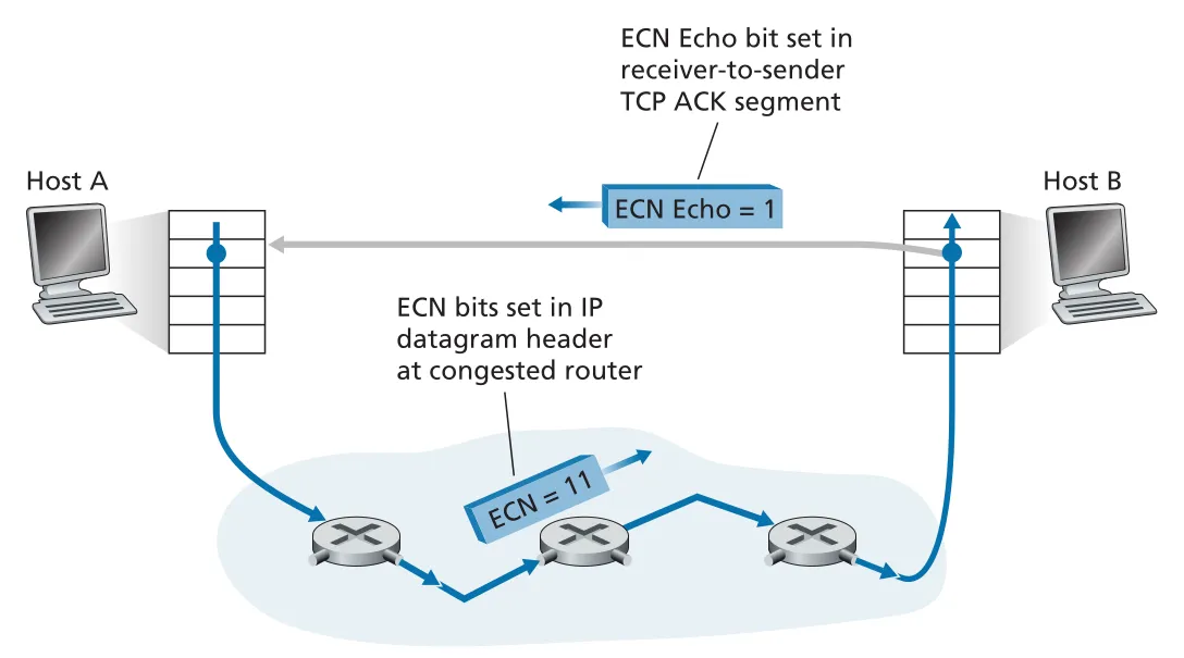 Figure 3.55 · PDF p. 286 · router가 IP datagram에 ECN을 mark하고 receiver가 TCP ACK의 ECE bit로 sender에게 알린다
delay-based congestion control은 packet loss가 생기기 전에 queueing delay 증가로 congestion onset을 감지하려는 방식이다. TCP Vegas는 ACKed packets의 RTT를 측정하고, 최소 RTT인 RTTmin을 uncongested path의 기준으로 둔다. 현재 에서 queue가 없다면 가능한 throughput은 이다. 실제 measured throughput이 이 값에 가깝다면 아직 path가 congested되지 않았다고 보고 rate를 늘릴 수 있다. 실제 throughput이 훨씬 작으면 queue가 쌓여 delay가 커졌다고 보고 sending rate를 줄인다.
Vegas의 직관은 “Keep the pipe just full, but no fuller”다. bottleneck link가 놀지 않도록 pipe는 채우되, queue가 길어져 delay만 늘어날 정도로 더 채우지는 말자는 뜻이다. BBR은 Vegas 계열의 delay/rate 관찰 아이디어를 발전시킨 congestion control로, CUBIC 같은 non-BBR senders와의 fairness도 고려한다.
3.7.3 Fairness
fairness는 bottleneck link rate가 이고 개의 TCP connections가 큰 file을 전송할 때 각 connection의 average transmission rate가 대략 가 되는 성질이다. TCP AIMD는 이상화된 조건에서 fairness로 수렴하는 직관을 제공한다.
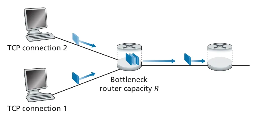 Figure 3.56 · PDF p. 288 · 두 TCP connection이 하나의 bottleneck link capacity R을 공유하는 fairness 모델
두 TCP connections가 같은 MSS와 RTT를 가지고 congestion avoidance mode에서만 동작한다고 하자. 둘 다 loss가 없으면 각자 를 1 MSS per RTT만큼 증가시키므로 throughput point는 equal-increase 방향으로 움직인다. 두 throughput의 합이 을 넘으면 packet loss가 발생하고, 둘 다 multiplicative decrease로 window를 절반으로 줄인다. 이 additive increase와 multiplicative decrease를 반복하면 throughput point는 equal bandwidth share line 근처로 수렴한다.
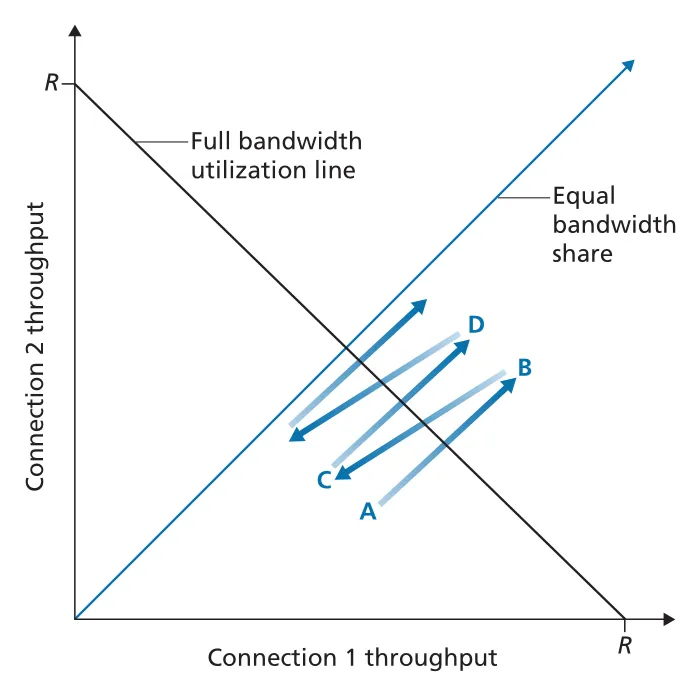 Figure 3.57 · PDF p. 289 · AIMD는 full utilization line과 equal bandwidth share line 근처로 throughput을 수렴시킨다
다만 실제 Internet에서는 fairness가 깨질 수 있다.
| 원인 | 왜 불공정해지는가 |
|---|---|
| different RTT | RTT가 짧은 TCP connection은 ACK가 더 자주 와서 congestion window를 더 빨리 키운다. |
| UDP traffic | UDP는 built-in congestion control이 없어 rate를 줄이지 않을 수 있고, TCP traffic을 crowd out할 수 있다. |
| parallel TCP connections | 한 application이 여러 TCP connections를 열면 각 connection이 별도 share를 받으므로 전체 bandwidth share가 커진다. |
따라서 TCP fairness는 “TCP AIMD가 같은 조건의 competing TCP flows 사이에서 bandwidth share를 맞추려는 성질”이지, 모든 transport traffic이 자동으로 공평해진다는 뜻은 아니다.
3.8 Evolution of Transport-Layer Functionality
Internet transport layer의 대표 protocol은 UDP와 TCP지만, 둘만으로 모든 application 요구를 깔끔하게 만족시키기는 어렵다. UDP는 단순하고 빠르지만 reliability, congestion control, connection management가 거의 없다. TCP는 많은 기능을 제공하지만 byte-stream ordering, head-of-line blocking, kernel/OS update cycle, handshake latency 같은 제약이 있다. 그래서 transport-layer functionality는 TCP 자체의 여러 flavor와, UDP 위 application-layer protocol 형태로 계속 진화했다.
TCP 쪽에서는 TCP Tahoe, TCP Reno 같은 classic TCP 이후 TCP CUBIC, DCTCP, CTCP, BBR 등이 등장했다. 이들은 wireless link, large RTT/high bandwidth path, packet reordering, data center network, multipath, priority 같은 환경 차이에 맞게 congestion control, ACK handling, connection setup/teardown을 다르게 조정한다. 이제 “the TCP protocol”이라고 단일하게 말하기보다, 같은 TCP segment format과 fairness 목표를 공유하는 여러 TCP variants로 보는 편이 더 정확하다.
QUIC: Quick UDP Internet Connections
QUIC (Quick UDP Internet Connections)은 UDP 위에서 동작하는 application-layer protocol이다. QUIC은 secure HTTP의 transport 성능을 개선하기 위해 connection management, encryption, reliable data transfer, congestion control을 application layer에서 직접 제공한다. UDP를 아래에 두는 이유는 Internet middlebox와 OS kernel의 TCP 변경 속도에 덜 묶이고, application update timescale로 빠르게 protocol을 바꿀 수 있기 때문이다.
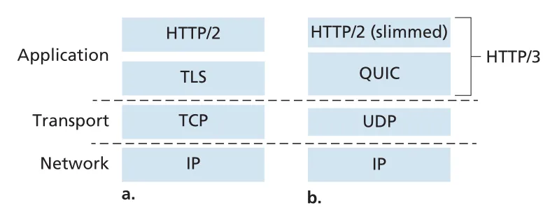 Figure 3.58 · PDF p. 292 · traditional secure HTTP stack과 UDP 위 QUIC 기반 HTTP/3 stack 비교
QUIC의 주요 특징은 다음과 같다.
| 특징 | 의미 |
|---|---|
connection-oriented and secure | TCP처럼 endpoints 사이에 connection state를 만들지만, connection setup과 authentication/encryption handshake를 결합해 RTT 비용을 줄인다. |
connection ID | source/destination connection ID가 QUIC connection state의 일부다. IP/port 변화에도 connection을 식별하는 데 도움이 된다. |
| encrypted packets | QUIC packets는 encrypted되며, secure transport를 기본 설계에 포함한다. |
streams | 하나의 QUIC connection 안에 여러 application-level streams를 multiplexing한다. 각 stream은 reliable, in-order, bi-directional delivery abstraction이다. |
| per-stream RDT | reliable data transfer를 stream별로 제공해 한 stream의 loss가 다른 stream delivery를 막지 않게 한다. |
| TCP-friendly congestion control | QUIC congestion control은 TCP NewReno/Reno 계열 알고리즘과 유사한 원리를 사용해 TCP flows와 공존하도록 설계된다. |
HTTP/1.1 over TCP에서는 여러 HTTP requests가 하나의 TCP byte stream 위에 올라가면, 앞쪽 byte loss가 뒤쪽 HTTP message delivery를 막는 HOL blocking (head-of-line blocking)이 생긴다. TCP는 connection 전체에 대해 reliable, in-order byte delivery를 제공하므로 lost bytes가 복구될 때까지 뒤의 bytes를 application에 넘길 수 없다.
QUIC/HTTP/3에서는 여러 HTTP objects가 서로 다른 QUIC streams로 나뉜다. UDP segment 하나가 lost 되어 어떤 stream의 data가 빠지더라도, 그 segment에 포함되지 않은 다른 streams의 messages는 계속 receive/deliver될 수 있다. 즉 QUIC은 UDP의 unreliable datagram service 위에 stream 단위 reliability를 올려 HOL blocking 범위를 줄인다.
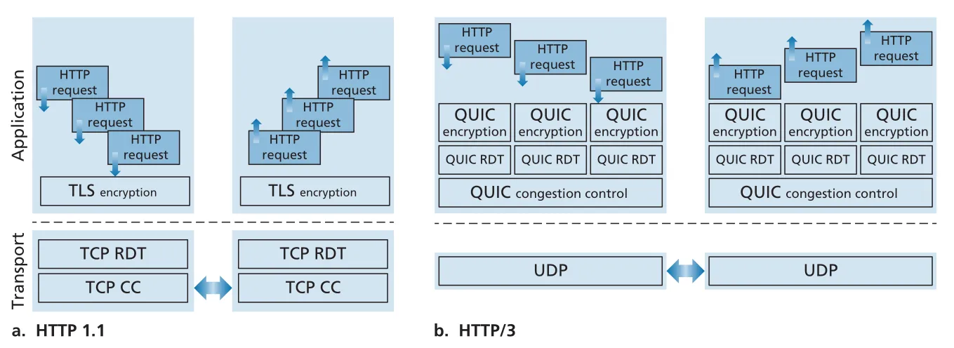 Figure 3.59 · PDF p. 293 · HTTP/1.1은 TCP RDT/CC 위 단일 byte stream, HTTP/3은 QUIC per-stream RDT와 congestion control을 UDP 위에 둔다
QUIC은 이 장의 많은 주제를 한 번에 묶는다. application-layer protocol이지만 내부적으로는 ACK, retransmission, timer, sequence/packet number, congestion control, connection setup, encryption을 다룬다. 따라서 transport 기능은 반드시 transport layer protocol 내부에만 있어야 하는 것이 아니라, 필요하면 application layer에서도 구현될 수 있다는 점을 보여준다.
3.9 Summary
transport layer는 network application이 직접 사용하는 end-to-end service interface를 제공한다. UDP는 multiplexing/demultiplexing과 checksum 중심의 no-frills service이고, TCP는 reliable data transfer, flow control, connection management, congestion control을 포함한 richer service다. 하지만 transport service는 underlying network-layer service에 의해 제한된다. network layer가 delay guarantee나 bandwidth guarantee를 제공하지 않으면, transport layer가 그것을 완전하게 보장할 수 없다.
reliable data transfer는 unreliable channel 위에서도 만들 수 있다. 핵심 재료는 ACK, NAK, sequence number, timer, retransmission, checksum, receiver buffering이다. rdt1.0에서 시작해 rdt2.x, rdt3.0, pipelining, Go-Back-N, Selective Repeat로 갈수록 loss/corruption/delay가 있는 현실적인 channel과 성능 요구를 더 잘 다룬다.
TCP는 이 원리를 Internet transport protocol로 구현한다. byte-stream service를 segment로 나누고, sequence number와 acknowledgment number로 ordering과 recovery를 관리한다. EstimatedRTT, DevRTT, TimeoutInterval로 retransmission timeout을 조정하고, fast retransmit으로 timeout을 기다리지 않고 loss를 복구한다. 기반 flow control은 receiver buffer overflow를 막고, three-way handshake와 FIN/ACK state transition은 connection lifecycle을 관리한다.
congestion control은 network 전체의 건강을 위한 mechanism이다. congestion을 방치하면 queueing delay, buffer overflow, redundant retransmission, upstream bandwidth waste가 누적되어 throughput collapse로 이어질 수 있다. Classic TCP는 end-to-end 방식으로 loss event를 congestion signal로 보고, slow start, congestion avoidance, fast recovery, AIMD로 를 조절한다. 이후 ECN, delay-based congestion control, CUBIC, BBR 같은 방식이 packet loss 이전의 congestion onset이나 high bandwidth/high RTT 환경을 더 잘 다루도록 발전했다.
이 장은 network edge의 두 층, application layer와 transport layer를 마무리한다. 다음 network layer에서는 end systems 안의 process-to-process delivery를 넘어서, network core가 datagram을 source host에서 destination host까지 어떻게 forwarding/routing하는지를 다룬다.
Review and Practice Targets
Chapter 3의 문제와 lab은 다음 능력을 점검하도록 설계되어 있다.
| 범위 | 연습 초점 |
|---|---|
| Sections 3.1-3.3 | port number, socket, multiplexing/demultiplexing, UDP checksum, UDP vs TCP service model |
| Section 3.4 | rdt FSM 해석, alternating-bit protocol, GBN/SR window movement, sequence number space 조건 |
| Section 3.5 | TCP sequence/ACK number 계산, RTT/RTO 계산, retransmission scenario, flow control, connection setup/teardown state |
| Sections 3.6-3.7 | congestion cost, cwnd/ssthresh evolution, slow start/congestion avoidance 판별, AIMD throughput/fairness 계산 |
| Programming assignment | alternating-bit protocol 또는 GBN sender/receiver 구현, timer interrupt와 simulated unreliable channel 처리 |
| Wireshark TCP lab | trace에서 RTT, retransmission, window behavior, flow control, congestion control 추론 |
| Wireshark UDP lab | UDP header fields와 checksum 계산 확인 |
Van Jacobson 인터뷰는 TCP congestion control의 역사적 배경을 잘 보여준다. 중요한 포인트는 congestion 문제를 “왜 실패하는가?”가 아니라 “원래 TCP가 어떻게 작동하고 있었는가?”라는 질문으로 바꾸면서 ACK clocking의 역할을 이해했다는 점이다. 이 장에서 self-clocking, slow start, AIMD를 연결해 보는 데 좋은 맥락이 된다.